Archive for the 'Floppy Emu' Category
Floppy Emu Chameleon Firmware
Here’s a fun party trick: firmware for the Floppy Emu disk emulator that emulates a 5.25 inch floppy drive, but then reconfigures on the fly as a Smartport hard disk emulator. Why is this useful? It’s not obvious at first, but if you’re a Floppy Emu owner with an Apple IIgs and an Apple 3.5 inch floppy drive, read on. Or if you just like nifty hacks, this one’s for you.
The IIgs supports daisy-chaining up to six disk drives – a great feature. Unfortunately there are strict rules about what order the drives must appear in the chain, depending on their type, and there are further limitations on which drives can be used as boot drives. So there are some perfectly reasonable drive combinations that are impossible in practice.
The best example is a Floppy Emu configured for Smartport hard disk emulation mode, combined in a daisy chain with an Apple 3.5 inch floppy drive. IIgs owners want to boot from the Emu’s Smartport HD most of the time, but still want the flexibility of having a 3.5 inch drive for the occasional physical floppy. Apple says no. Drive ordering rules require the 3.5 inch drive to appear before any Smartport drives, and only the first drive in the chain can be used to boot the computer. The IIgs will always attempt to boot from the Apple 3.5 inch drive. So the desired configuration is impossible, and this is a limitation of the Apple IIgs design rather than anything specific to the Floppy Emu.
But wait… maybe there’s a hope. Eric Jacobs points out there’s a table that controls the boot priority of the drives in the daisy chain, located in Apple IIgs memory at address E10FC0. This table is initialized during a cold boot and gives the first drive first priority. If you edit the memory table and then restart with a warm boot, you can force the IIgs to boot from a different drive, like the Emu’s Smartport HD instead of the Apple 3.5 inch drive.
That’s good news, and it provides a theoretical solution, but the actual practice is lousy. You have to turn on the computer, interrupt the boot process with control-reset, enter the Apple II system monitor with CALL -151, and manually edit the memory table using arcane debug commands. Then you finish the process by forcing a jump to the warm start address. Several months ago I confirmed that this process works, but it’s not very user-friendly, so I dropped it.
Here’s where part two of this party trick comes into play. The IIgs also supports 5.25 inch floppy drives, which must be connected in the daisy chain after any 3.5 inch and Smartport drives, but nevertheless normally get a higher boot priority than the other drive types. I can leverage this fact to make the Floppy Emu appear as a 5.25 inch drive, which loads a small bootstrap program that edits the memory table. Then the Floppy Emu auto-reconfigures itself as a Smartport drive, and the bootstrap program performs a warm start of the IIgs.
Here’s the play-by-play process:
- Connect the Apple 3.5 inch drive to the Apple IIgs
- Connect Floppy Emu to the Apple 3.5 inch drive
- Turn on the Apple IIgs
- Floppy Emu configures itself as a 5.25 inch drive
- Floppy Emu provides a hard-coded disk image containing a bootstrap program
- Apple IIgs boots from the 5.25 inch bootstrap disk
- Bootstrap program displays a splash screen and modifies the IIgs memory table
- Floppy Emu reconfigures itself as a Smartport HD
- Bootstrap program performs a restart of the IIgs
- IIgs boots from the Floppy Emu’s Smartport HD
The net result is that it’s now possible to have an Apple 3.5 drive and a Floppy Emu Smartport HD in the same daisy chain, while booting from the Emu’s HD – something that was previously impossible.
Watch the video carefully, and you’ll see a text screen flash by that says “Big Mess o’ Wires, rebooting from smartport unit 2…” That’s the bootstrap program at work. Unfortunately my composite video to HDMI adapter creates ~5 seconds of blackness whenever the IIgs first powers on, or changes between text and graphics modes, so this isn’t the greatest video. The whole process from power on to Smartport HD boot only takes about 10 seconds, with no user intervention needed.
It works, but there are still some details to resolve. There’s a timing dependency between when the computer boots, when the Floppy Emu reconfigures as a Smartport HD, and when the bootstrap program restarts the IIgs. I used hard-coded delays that work on my system, but may not work for other people. Get these delays wrong, and the IIgs will fail to boot from the bootstrap disk, or will restart and try to boot from the Smartport HD before the Floppy Emu has reconfigured itself. A better solution would involve some kind of control signal between the IIgs and the Floppy Emu to orchestrate the timing, rather than relying on fixed delays with no feedback.
A second problem is that this trick is incompatible with my (yet to be released) Daisy Chain Adapter. The Daisy Chain adapter senses what type of disk the Floppy Emu is configured to emulate, and acts accordingly. It can’t support a Floppy Emu that suddenly transforms from a 5.25 inch drive into a Smartport HD in the middle of operation. There needs to be some way for it to detect that this has happened, or be notified that it’s happened, so it can reset its own internal state. But so far I’m lacking any practical ideas on how to do that. In the worst case I can simply warn users that this firmware trick is incompatible with use of the Daisy Chainer, but that would be a shame.
Read 5 comments and join the conversationDaisy Chainer Update

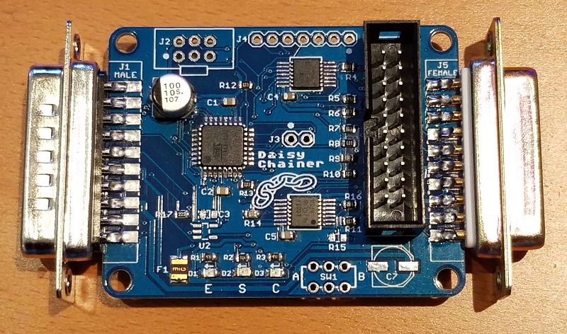
Picking up after a month hiatus, I’ve assembled one unit of the Daisy Chainer for the Floppy Emu disk emulator, and it seems to be working. I’ve only had time to do brief testing, but so far so good, and the power/ground weirdness observed in the breadboard prototype appears to be gone. Some parts that I planned for proved to be unnecessary, so you can see a few unpopulated footprints on the board. To be removed in a version 2 PCB, maybe.
The Daisy Chainer board makes it possible to insert a Floppy Emu anywhere into your daisy chain of Apple II drives, with other floppy drives before and/or after it in the chain. It provides a nice improvement in flexibility for Apple IIGS owners and other Apple II users with complex drive setups.
As seen in the photos, I ultimately went with the “smart” design that I discussed earlier, with an ATMEGA48 microcontroller in charge of the show. But the firmware couldn’t be simpler: it’s just a 12-instruction loop that reads some inputs, updates three bits of state, and uses a lookup table to determine some output values. I’m still not convinced this was the best approach, since I could have performed the same function with just 2 or 3 basic logic ICs. But the microcontroller is no more expensive, and it’s more compact, and more flexible, so maybe it’s OK even if it does feel like overkill.

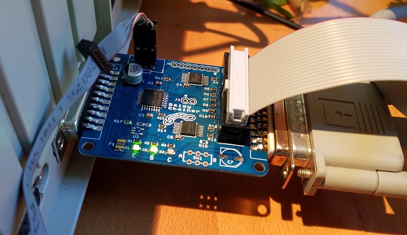
Usage is simple: just plug it in and turn it on. The male DB19 (at left in the photo) connects to the upstream drive in the daisy chain, or directly to the computer if there’s no upstream drive. The female DB19 (at right) connects to the downstream drive, and the Floppy Emu connects to the 2×10 header with its ribbon cable. There are no user controls and nothing to configure. The only nod to “human interface” is a set of three LEDs that might be useful for debugging, or for curious nerds. They show the status signals used for detecting the drive type of the Floppy Emu and the downstream drive.
Read 12 comments and join the conversationPCB Autorouting

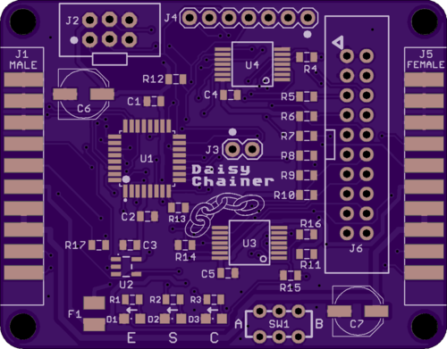
The Apple II Daisy Chainer for Floppy Emu is done, and I’ve ordered a few PCBs made for testing. This proved to be a surprisingly challenging board to lay out and route the traces. It’s a simple two-layer board, and I wanted to keep it as small as possible, so the signal routing quickly became very congested. Hand-routing of the first 40 traces took almost a whole day of tedious work, so I finally gave up and tried autorouting the remaining 80 traces. And it worked! The result looked pretty good, too. I’m curious to know how autorouting has turned out for other hobbyists. Have you ever autorouted nearly an entire board? What were the results?
I haven’t had good results with Eagle’s built-in autorouter, so for recent projects I’ve been using a stand-alone autorouting software package called Freerouting. It’s a Java-based app with a slightly awkward UI, but it’s impressively powerful. First you export your Eagle board file in .DSN format, using a script provided by Freerouting. Then you import the DSN file into Freerouting and let it work, running for about 1 to 15 minutes. When it’s finished you can export an Eagle session script, which will rip up all your old tracks and lay down the new ones calculated by Freerouting.
Obtaining good autorouting results requires careful setup of Eagle’s design rules. For example, the default might be to use 8 mil traces with 8 mil minimum spacing between traces, but power and ground might be treated as a separate net class requiring 20 mil traces for extra current-carrying capacity. The design rules also define what size drill to use for vias, and how close to the edge of the board it’s OK to route traces. The autorouter takes all of these constraints into account when it does its job.
So what’s not to like about the autorouter? Can a skilled human do a better routing job? Why not autoroute everything? Here are a few drawbacks that I found.
Fixed Component Placement – When I route by hand, I’ll sometimes discover that I’ve placed a component in the middle of a chokepoint for PCB traces. If the placement isn’t critical, I can move the component to make routing easier. The autorouter can’t do this, at least not that I’ve seen. It treats the component placements as fixed and immutable, even when nudging a resistor 10 mils to one side could make a huge difference.
In theory there’s no reason that the autorouter couldn’t handle changing component placements. Additional constraint information could be supplied, providing a bounding box of acceptable placements for each component, or tagging some component placements as critical and non-movable.
Unnecessarily Aggressive Routing – If the design rules say that 8 mils is the minimum acceptable spacing between traces, the autorouter will often stack traces 8 mils apart even when there’s plenty of room for wider spacing. It’s too aggressive – pushing spacing to the limit when it doesn’t need to. In theory this shouldn’t be a problem, but it feels like poor design practice to me. To avoid the risk of accidental short circuits, I prefer not to push the PCB manufacturing limits except in those few areas of the board where there’s no alternative.
A good example is autorouting between adjacent pins of a 0.1 inch header. There’s roughly 30 mils of space between the metal rings that surround adjacent pins, providing enough space for an 8 mil trace with 11 mils of space on both sides. But Freerouting often placed such traces off-center, with 8 mils of space on one side and 14 on the other. It met the design rules, so from its viewpoint there was no reason not to do it that way.
In practice an 8 mil minimum spacing is already conservative, and most PCB manufacturers can do 6, 5, or 4 mil minimum spacing. So it’s unlikely this behavior will cause any trouble here, but it might for other boards with smaller minimum spacings.
Nuances of the “Best” Routing – Once Freerouting finds a routing solution, it tries to optimize it by minimizing the total trace length and the number of vias. These are good optimizations, but sometimes I want other considerations to trump them. For example when I route manually, I try very hard to minimize vias in power and ground traces. I would be happy to add 5 extra vias elsewhere if I could eliminate one via for power or ground. Freerouting doesn’t support this kind of trade-off, so all vias are treated equally.
A related consideration is the number of power and ground paths. The autorouter considers a pin to be powered if there’s any combination of traces leading from the power supply to the pin. Only one such path is required, and the result is a logical tree with the supply at its root and the power pins at the end of the branches. But when I route manually, I often connect branches back together, creating multiple paths from the power supply to the pin. I use the same approach for grounds. The goal is to minimize the voltage difference between power and ground points on different regions of the board.
The autorouter doesn’t care about visual aesthetics, and normally I don’t either. But when two possible routes are equally effective, I normally choose the one that’s similar to other traces I’ve already routed. It makes the board’s interconnections easier to understand at a glance.
Freerouting also doesn’t account for any potential analog signal effects, at least not that I’ve seen. If it’s important to minimize the trace length for a specific signal, or match the trace lengths of two signals, it can’t help. It also doesn’t consider problems like the parasitic capacitance formed by two long parallel traces. Depending on the signals, the signal speed, and other factors, a skilled human might choose to route two signals on non-parallel paths even if parallel routing was the shortest distance with the fewest vias.
Do you have any autorouting secrets to share? Let’s hear them!
Read 8 comments and join the conversationSimulating Disk Sounds
If you’ve ever used an Apple II computer, then you’ll remember the click-clack-whack sounds of a 5 1/4 inch floppy drive. The internal stepper motor moves between tracks on the disk, and every step makes an audible sound. When the computer first boots, it makes an unforgettable buzzing sound as the stepper is repeatedly whacked into the mechanical stop at track 0. By comparison, running an Apple II with a Floppy Emu disk emulator is silent. Should we add back some of that old-fashioned noise?
I built a simple circuit with a 12V relay that’s controlled by the Phase 0 signal on the disk interface. Phase 0 is one of the four control signals for the disk stepper motor, and ignoring the other three signals won’t produce totally authentic sounds, but it’s pretty close. The circuit uses a transistor, so the coil current won’t be drawn directly from Phase 0. The relay here isn’t actually controlling any load – the coil is energized simply to create a mechanical click sound. And it works! Here’s the demo:
Relays can be awkward to work with, they require a comparatively large amount of current compared to digital circuits, and a diode to prevent dangerous voltage spikes when the coil shuts off. What about using a speaker element instead? I modified my circuit to replace the relay with a tiny speaker that I had in a drawer, and change the driving voltage from 12V to 5V. To be honest I have no idea what the speaker’s specs are or how much current this might be drawing from the supply, but it works:
I was considering integrating a click relay or speaker into the much-discussed Floppy Emu daisy chain adapter. What do you think? After running these tests, I’m less excited about the idea than I was initially. It’s fun for a few minutes, but after that I’m concerned it would grow irritating. I could include a disable switch, but it seems foolish to incur the expense and design time of adding this extra feature if most people will turn it off anyway. Relays and speakers aren’t exactly cheap either, at around $1.00 to $1.50 in the quantities I’m looking at, making them more expensive than a microcontroller. Rapid on-off switching of the coil or speaker current will also generate electrical noise in the power supply and disk I/O signals, increasing the chances of disk errors if the signal quality is already marginal. So even if cost isn’t an issue, malfunctions are still a risk.
Of the two versions, I think I prefer the relay’s more authentic sound, but the speaker would be easier to work with and probably less likely to cause electrical trouble. Either one could work. Aside from the difference in tone, the speaker also produces a different series of clicks than the relay. The speaker can respond more quickly to changes on Phase 0, while the relay’s mechanical design likely misses any Phase 0 pulse that’s shorter than a few milliseconds.
If most people feel this is a compelling extra feature, and they wouldn’t mind the few extra dollars in cost, that’s great. But if the reaction is more mixed or merely “would be nice”, then I’ll probably leave it out.
Read 18 comments and join the conversationJumbo OLED Fun

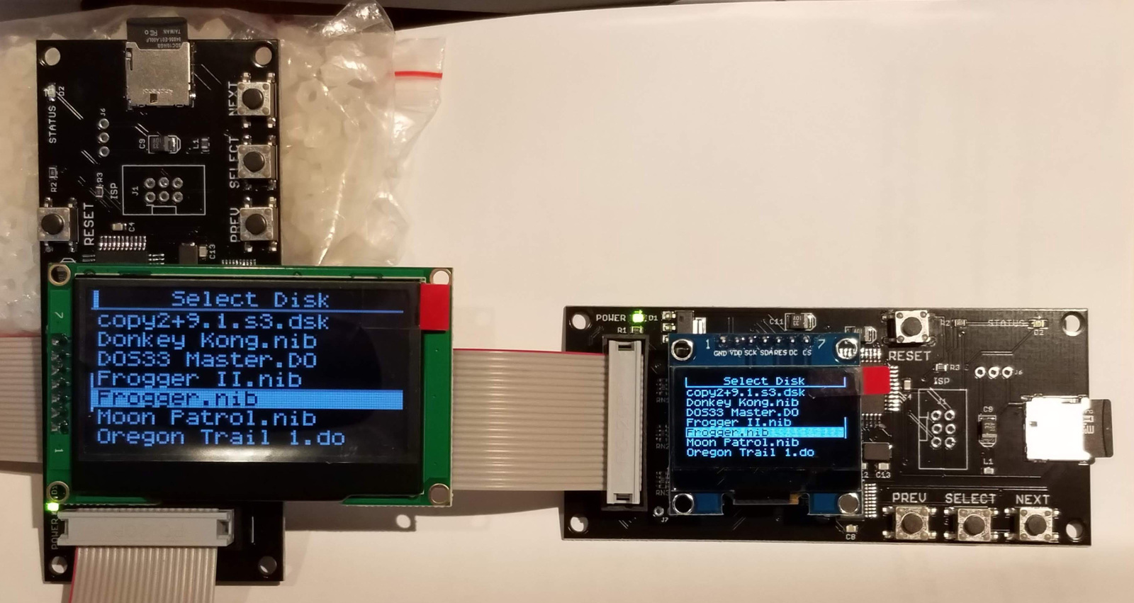
A few days back, a discussion on the Apple II Facebook group asked about large format Floppy Emu displays for people with vision difficulties. Here’s a 2.42 inch OLED that’s a simple drop-in replacement for the OLED in Floppy Emu Model C. With more than 3x the screen area of the standard OLED, that’s a big increase in display size!
This particular OLED was $17.99 and can be purchased here. The only minor issue is that the rightmost column of pixels appears on the left side of the display – some sort of off-by-one error.
Read 15 comments and join the conversationDaisy Chain Design Vote
Vote for your preferred Floppy Emu daisy chain design option! I’ve been working on this concept for several weeks, and wrote about it here, here, here, and here. I’ve now realized there are two different paths I could follow, with different feature sets and likely costs. For those who are potentially interested in the daisy chain adapter, I’d like to know which option you’d prefer.
Option 1 is what I’ve been discussing all along. It’s an intelligent adapter based on a microcontroller or CPLD, that allows for pretty much any valid combination of Floppy Emu mode and daisy chained drive types. It auto-detects the modes and types, so there’s nothing to configure. It has some LEDs to show the detected types or other debug info. And it also fixes some other minor problems with Floppy Emu daisy chaining like this one. I’m about 90% sure it will work, but there may be weird rare bugs. Retail price will likely be somewhere in the 30’s (very rough guess).
Option 2 is a “dumb” adapter, somewhat similar to the retired Universal Adapter for Floppy Emu Model A. It’s a fixed configuration of a few 7400-series logic chips. It supports the most useful combinations of Floppy Emu mode and daisy chained drive types, but does not support all combinations. Drive types are not auto-detected, and must be manually chosen with a switch. There are no status or debug LED’s. It doesn’t fix the other minor problems. I’m 100% sure it will work. Retail price will likely be somewhere in the 20’s (very rough guess).
| Option 1 | Option 2 | |
| Design | Smart | Dumb |
| Disk Type Detection | Automatic | Manual Switch |
| Configurations | Emu 3.5 with chained 3.5 Emu 3.5 with chained Smartport Emu 3.5 with chained 5.25 Emu Smartport with chained 5.25 Emu 5.25 with chained 5.25 |
Emu 3.5 with chained 3.5 Emu Smartport with chained 5.25 Emu 5.25 with chained 5.25 |
| Status LEDs | Yes | No |
| Minor Fixes | Yes | No |
| Development Time | Slower | Fast |
| Confidence | 90% | 100% |
| Cost | $30’s | $20’s |
For the sake of this discussion, Unidisk 3.5 emulation mode counts as Smartport. Note that neither option 1 nor 2 supports Emu Smartport with chained Smartport.
Option 1 is certainly the most flexible, and has the best cool factor. With a change of firmware, it could even do other cool disk-related things I haven’t dreamed of yet. And I’ve already sunk a lot of time into designing it.
But I can’t escape the feeling that I’ve lost sight of the core purpose and over-engineered a solution. There’s a lot to be said for a keeping-it-simple design, and that’s what option 2 is. Auto-detection is very nice, but is flipping a switch really so bad? Would anybody really miss the two disk configurations this option lacks? Option 2 could be built easily, but option 1 would have to be programmed and tested after assembly, adding time and cost.
What do you think? Despite how much time I’ve spent working towards option 1, I’m leaning towards option 2. Because it’s probably more important that this thing works rock-solid in the common use cases, and is as affordable as possible, than that it has every whiz-bang feature that only 1% of people will care about.
Read 20 comments and join the conversation
