

Archive for the 'Floppy Emu' Category
New Demo Video
I put together a new demo video for the Floppy Emu Model B, since the old videos had become hopelessly out of date. Enjoy!
Be the first to comment!DB-19 Substitute, Take Two

BMOW’s product Floppy Emu needs a male DB-19 connector to mate with vintage Apple computers, but these connectors haven’t been manufactured in decades. For two years I’ve been scraping by with “new old stock” DB-19’s from warehouses around the world, but that supply has almost completely dried up. I recently found a few hundred more, but it’s clear that the end will come sometime in 2016. To prepare for the worst, I’ve been working on a design for a DB-19 substitute. After more experiments, today I decided that this path has reached a dead end.
The current DB-19 adapter for Floppy Emu is shown at left, in the photo above. It consists of a small PCB with an edge-mounted male DB-19 at one end, and a 10×2 shrouded header connector at the other end. A ribbon cable plugs in to the 10×2 header, and the DB-19 plugs into the computer’s external disk port, and everything is great.
Designing a Substitute
The basic idea of a DB-19 substitute is to replace the male DB-19 with sections of 0.1 inch male header arranged in a DB-19 pattern, while keeping everything else more or less the same. I first explored this idea a year ago, and the prototype worked reasonably well, but had its share of problems. The 0.1 inch pin spacing didn’t quite match the 0.109 inch spacing of a D-SUB connector, and it put square pins into round holes. Without a surrounding shield, it was too easy to misalign the substitute connector while plugging it in, so I added two rectangular LEDs as structural elements to serve as mechanical guides. It sounds dodgy, but it passed some quick tests on several different Apple computers. Then I put the prototype away in a drawer, and didn’t think about it again.
This week I received a new PCB for what I hoped would be the final DB-19 substitute design. I shrunk the overall size of the PCB, and gave it a trapezoid shape with rounded edges to invoke the spirit of a real D-SUB. I split up the 0.1 inch headers into a larger number of smaller sections, so the average offset from the nominal 0.109 inch spacing was reduced. And taking a popular suggestion from the first prototype, I made the LEDs into more than mere mechanical guides – now they light up! It’s a pretty cool effect. A side-by-side comparison of this new DB-19 substitute with the current model DB-19 adapter is shown above, and a rear view of the same connectors is below:

Quality Control Failure
The new DB-19 substitute passed all my initial tests, and everything was looking good. But once I started testing more carefully, I realized that the connection wasn’t solidly reliable. It worked 100% of the time on my Mac Plus, Apple IIgs, and a borrowed Apple IIc+. But when plugged into the daisy chain connector of an Apple 3.5 Drive, it only worked about half the time. And when plugged into an Apple IIc, it never worked, unless I pushed on the connector with my finger during disk I/O. Ugh. At first I thought maybe this new DB-19 substitute had some new problem, but when I tested last year’s version more carefully, it had the same issues.
I think there are several things preventing this from working reliably. While putting square pins into round holes sounds crazy, I think that’s the least of the problems. What’s more significant is that the diagonal length of each pin’s cross section is probably slightly different than the diameter of the round pin that’s supposed to be there. Combined with the slight misalignment of some pins, I believe this leads to weak or no contact for those pins inside the female connector. I don’t know if the female’s interior has flat wipers, or a true round receptacle. Maybe different models of Apple computer have different receptacle designs. It doesn’t seem like a good idea to rely on that.
The other problem is the vertical height of the whole DB-19 substitute assembly. The current DB-19 adapter has only a male DB-19 at one end, with a height of about 3/8 of an inch. But the new, reduced size DB-19 substitute assembly has a PCB directly behind the pins, with a height of about 5/8 of an inch. For most Apple computers, the extra height is no problem. But for a few systems with recessed disk connectors, the extra bulk bumps into the plastic above the recessed connector, preventing it from being fully plugged in. On an Apple IIgs, it just barely fits. On the daisy chain connector of an Apple 3.5 Drive, it doesn’t fit.
Alternate Ideas
What to do? I’m probably going to abandon the idea of using 0.1 inch male header, as it just doesn’t seem reliable. Another option is to use 19 individual D-SUB crimp pins, soldered into the DB-19 substitute PCB. I built one of these last year, and it’s shown at left in the photo below, along with the first generation of the 0.1 inch male header substitute.

The version with the D-SUB crimp pins is definitely more reliable, but it’s a nightmare to assemble. Crimp pins aren’t designed to be soldered into a PCB like this, and to prevent solder bumps on the pin side from shortening the effective pin length, the pins need to be soldered from the “wrong” side of the board using an ugly technique. Individual pins won’t stay straight while soldering, so a female DB-19 must be used as a jig during assembly. And when it’s done, the crimp portion of each pin must be cut off with shears. The current DB-19 adapters are factory assembled with a mostly automated process. This crimp pins design would require a cumbersome manual process, driving up the cost, if the factory was even willing to do it. And the problem with the height of the assembly would still remain.
The other option is to find a D-SUB factory that could manufacture new male DB-19 connectors. I checked into this last year, and it looked like a tough road. Negotiating that kind of manufacturing deal is difficult for someone like me, with no industry contacts or big name credibility. Most places didn’t even respond to my emails. From those that did, it looked like setup costs would be around $10,000 before they could make even a single part. Given the small scale of my business, that’s not realistic. I’d have to buy a virtual lifetime supply of DB-19 connectors, and hope that Floppy Emu sales continued on pace through 2030 or so.
This just became my new #1 problem. I’m going to work on brainstorming other solutions involving D-SUB crimp pins or other round pins, and also make another set of inquiries for manufacturing new DB-19 connectors. The clock is ticking…
February 23 Addendum
After mulling this over for a while, I’m coming to the conclusion that I should get new DB-19 connectors manufactured, even if it costs $10,000. It’s the only solution I’m confident will work reliably. Everything else I can think of is a trade-off of quality for cost, and nobody’s going to be happy if I switch to a new style of DB-19 substitute that’s not always reliable or that has trouble fitting certain computers.
The cost of manufacturing new connectors is high, but the alternatives aren’t free either. I priced out one possible alternative involving an empty DB-19 male housing and 19 crimp pins, and it would cost about $5 per connector including the increased labor cost to assemble it. At the current sales rate, I’d be spending about $2000/year for a solution that’s inferior to a real DB-19. Compared to that, $10,000 doesn’t seem quite so unreasonable. The other alternatives I described earlier would be cheaper to build, but seem to have reliability problems, so they’re not really viable.
I’ve been using the number $10,000 as a rough figure, but it may be less than that. Assuming the best quote I received a year ago is still valid, it would be roughly $8000 to get 10,000 DB-19 connectors manufactured and delivered. That’s about one third of the total profit I made from all BMOW product sales last year. So it’s a big number, but not completely out of the question. I don’t need 10,000 DB-19 connectors, but I could probably resell some of those over the next few years and recoup $1000 or so of the manufacturing cost.
I’ve been talking with a person at IEC about splitting a new manufacturing run with them, which would help a lot if we can reach an agreement. Another possibility is to run a GoFundMe campaign and solicit donations to “save the DB-19”. If I could get enough vintage Apple enthusiasts to chip in $10 or so, it might make a significant dent in the manufacturing cost. Maybe I could put the names of the largest donors in the silkscreen of the adapter PCB.
At the end of it all, there’s just something cool about the idea of being the guy who resurrected the DB-19. Then the world can stop seeing sad pleas like this one. Maybe I’m insane, but that’s got to be worth something. 🙂
Read 24 comments and join the conversationSD Card SPI Initialization
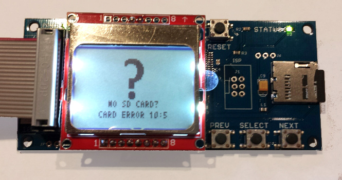
What happens when two devices share the same SPI bus? With a good design, each device is enabled one at a time for use of the bus, and they coexist without problems. With a bad design, SPI communication that’s intended for one device is sent to the other, leading to confusion and buggy behavior. In the Floppy Emu disk emulator, the SPI bus is shared between an SD card and an LCD display. As it turns out, it had a bug like this that escaped notice for almost two years, with the occasionally flaky behavior wrongly attributed to bad SD cards, faulty boards, or the phase of the moon. Doh!
The symptom was a “No SD card” message, with error code 10:5, when using a few specific models of SD card. During startup, the Floppy Emu firmware was sending SPI commands to the LCD to draw an image, then sending SPI commands to the SD card to initialize it. In rare circumstances, the initial communication with the LCD was confusing the SD card, leaving it in a state where it refused to respond to any further commands until the power was turned off and on. This caused the Emu to think no card was present. The problem didn’t always happen 100% of the time, and it appeared to depend on the electrical characteristics of each board and anything attached to it. But for certain models of SD card, it happened so consistently that the only remedy was to use a different SD card.
My solution was simple: initialize the SD card before doing any LCD communication. Grab the new firmware with the fix here:
floppy-emu-1.0R-F13 – Mac Floppy
hd20-0.7E-F14.5 – Mac Floppy + Hard Disk and Lisa Floppy
apple-II-0.1K-F7 – Apple II, for Model B
apple-II-0.1K-F6 – Apple II, for Model A
SPI Mysteries
You might wonder how a problem like this could have gone unnoticed for so long. Looking back over two years of support emails, I only found four problem reports that could be retroactively attributed to this issue. In each case, the person was able to get things working by trying a different SD card, so we chalked up the problem as a damaged or flakey card. It was only recently that I received two reports from people who’d tried multiple cards, all of which failed with the “No SD Card” message and error 10:5. Following up on their hardware, I bought two suspect 16 GB cards (1, 2), and confirmed that they both just plain didn’t work. Ouch. I’ve now verified that the new firmware gets both these SD cards working, and also received confirmation from some other users that the new firmware gets their troublesome cards working too.
So what exactly was the problem? The frustrating answer is that I don’t really know, and my description of the issue intentionally glossed over some important details. It’s true that the LCD communication somehow confused certain SD cards, but I can’t explain why.

Here’s a simplified diagram of Floppy Emu’s SPI bus. The LCD and SD card are independently enabled by separate, active low signals LCDE and SDE. Because the AVR microcontroller operates at 5V, all its outputs are passed through a 74LVC244 buffer to step them down to 3.3V for the LCD and SD card (the 3.3V signal MISO is an output from the SD card, and doesn’t need level conversion). SDE also has a 10K ohm pull-up resistor to +5V, to ensure that the SD card is disabled when the AVR isn’t actively driving the signal, during reset and microcontroller startup.
The only way it should be possible for the SD card to be confused by LCD communication traffic is if SDE were asserted at the wrong time. Looking at the schematic and the firmware code, I just don’t see how that’s possible. The pull-up resistor ensures that the SD card will be enabled if the AVR isn’t actively driving it. And once the AVR does begin actively driving it, it drives SDE high (unasserted) until it’s ready to begin communication with the SD card. So the card should be disabled during the initial LCD communication, and should ignore whatever is happening on the SPI bus.
If I weren’t so lazy, I would put a scope on the SPI bus, and verify that SDE is truly unasserted during LCD communication. But I’m lazy, and didn’t do that.
A few hints point to an electrical problem. With some cards, the 10:5 error occurred more often when I had an AVR programmer attached to the SPI bus, even if the programmer wasn’t active. And with those same cards, seemingly trivial firmware changes would cause the error to appear and disappear. Sometimes I’d only get the error on half my attempts, so it wasn’t a deterministic problem.
Maybe poor circuit design causes a momentary noise spike on SDE, during startup and LCD communication. Ringing, ground bounce, or cross-coupling of signals might cause SDE to briefly appear asserted when it shouldn’t be, causing the SD card to try to interpret communications meant for the LCD. But if that were the case, I’d expect to see all kinds of similar communication errors with the SD card during normal operation.
Another possibility is that there’s something fishy going on with AVR pin PB4, which is also the SPI SS (slave select) pin. The datasheet mentions that there’s some special behavior related to this pin. But after reading that section of the datasheet, I don’t think that’s the cause.
My last theory is that the problem is caused by accidentally switching the SD card into 4-bit mode. SD cards can operate in three different modes: SPI, 1-bit SDIO, or 4-bit SDIO. The latter two modes use the card’s pins like a conventional data bus. I believe the details of 1-bit and 4-bit SDIO may be proprietary and require an NDA, and every hobbyist-made microcontroller project I’ve seen has used SPI instead.
The catch is that SD cards initially power on into 1-bit SDIO mode, and part of the SD card initialization process is to switch to SPI mode, which will remain active until power off. With the old firmware, during the Floppy Emu’s initial LCD communication, the SD card was still in 1-bit SDIO mode rather than SPI mode. I don’t know anything about 1-bit SDIO mode, but maybe the chip select input is used differently in that mode, and my LCD communication was accidentally triggering a switch to 4-bit SDIO mode. As I understand it, once switched to another mode, that mode will remain active until power off, which is consistent with the “zombie SD card” behavior I observed with certain cards under the old firmware. Hmmm…
Read 3 comments and join the conversationClearance Sale: $79 Floppy Emu Model A

While supplies last, the Floppy Emu Model A is on sale at a clearance price of just $79. If you’ve been waiting to add one of these hard disk / floppy disk emulators to your Apple computer collection, now is your chance. The response to the new Model B has been great – maybe a little too great, and I need to close out the remaining inventory of Model A hardware. If you’re a Macintosh or Lisa user, or an Apple IIgs/IIc/IIc+ user looking for a Smartport hard disk, this is a great value! See the compatibility table on the order page and the Model B announcement for more details on Model A vs B differences.
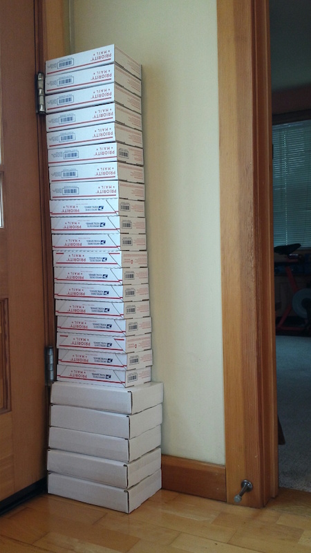
If I were a savvier businessman, I might have waited to introduce the Model B until my inventory of Model A hardware was gone. It’s not quite the Osborne Effect, but introducing a new model that kills demand for the old model may not have been the smartest move. Fortunately for you, my loss is your gain! The good news is that interest in the Model B has been strong. In the past I typically made about one sale per day, but recently it’s been much busier. This was the scene heading to the post office after the 3-day MLK Day weekend:
The Model A is the original Floppy Emu design that’s been featured here at BMOW for over a year. It emulates a classic Macintosh HD20 hard disk or 3.5 inch floppy disk, or a Lisa 3.5 inch floppy disk, or an Apple IIgs/IIc/IIc+ Smartport hard disk, or an Apple IIgs/IIc/IIc+ 5.25 inch floppy disk. Many people have purchased both a Model A and a Model B, to get a dedicated drive for each Apple computer in their collection. Don’t miss this chance to pick up a Model A at a great price!
Read 3 comments and join the conversationIntroducing Floppy Emu Model B

Today I’m excited to introduce the first significant update to the Floppy Emu disk emulator for Apple II and classic Macintosh computers: Floppy Emu Model B. The new Model B has the same disk emulation functions as the Model A and Universal Adapter, but with several new convenience features:
- Built-in Apple II Compatibility – Model B is directly compatible with the entire Apple II line, emulating a 5 1/4 inch disk, 3 1/2 inch disk, or Smartport hard disk. While Model A required a separate Universal Adapter for the best Apple II compatibility, Model B has the equivalent functionality built-in. Classic Macintosh and Lisa disk emulation is still supported too.
- microSD Card Support – The SD card slot is now a push-push microSD type, identical to what’s used in most mobile phones. This will make it easier to find suitable SD card media, since the older full-size SD cards are becoming rare.
- SD Card Hot-Swap – The SD card can be removed and re-inserted while the Floppy Emu is powered on.
- Improved Protection Circuitry – Model B features improved protection circuitry on the disk drive interface connector. This circuitry will help protect the Floppy Emu from electrical damage caused by voltage spikes and surges. It also eliminates the risk of potential damage if an Emu board running the Apple II firmware is inadvertently connected to a Mac or Lisa computer.
- Same Great Emulation Features – All of the time-tested Macintosh, Apple II, and Lisa disk emulation features from Model A are still present. Model B reads and writes emulated 140K, 400K, 800K, or 1.4MB floppy disk images, or hard disk images up to 2GB, if supported by your Apple computer. For full details, see the instruction manual.
If you’re new to Floppy Emu, it’s an external hardware device for vintage Macintosh, Apple II, or Lisa computers. It uses a removable SD memory card to mimic an Apple floppy disk and drive, or an Apple hard drive. The Emu behaves exactly like a real disk drive, requiring no special software or drivers. Floppy Emu is perfect for booting your favorite games, moving files between modern and vintage machines, and troubleshooting a computer without a working OS. Just plug in the Emu board, and you’ll be up and running in seconds.
Floppy Emu Model B is available for sale now. While supplies last, I’m also selling the remaining inventory of Floppy Emu Model A units for a reduced price. It’s disk emulation madness!
Read 35 comments and join the conversationOops! Laser Cut Material Thickness
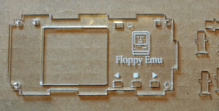
Manufacturing is hard. The thickness of my supplier’s clear acrylic material has magically increased 15%, meaning that the latest batch of Floppy Emu acrylic cases are impossible to assemble. The buttons and light pipes don’t fit in the cut-outs made for them, so this entire batch of product will have to be thrown out. I’m hoping the supplier will agree to re-run my order or provide a refund, but I’m not optimistic since 15% is just within their stated tolerance. An expensive mistake in manufacturing for me!
For the past year, I’ve been offering laser-cut case enclosures as a Floppy Emu accessory, and I’ve sold hundreds of the cases to happy customers. They’re made from 3.0 mm (nominal) clear acrylic. With all of my past orders from the laser cutter, the parts I received had an actual thickness between 2.73 mm and 2.83 mm, and my design accounts for that. A case assembled from the old ~2.75 mm thick material looks like this:
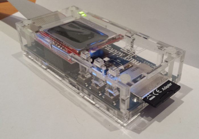
I just received a new delivery of parts yesterday, and the material thickness changed to 3.15 mm! Imagine if you were building a house with 8 foot ceilings, but some of the framing lumber was over 9 feet – it would never work. That’s the same magnitude of change I’m facing now. The buttons and light pipes are cut from the same material as the case body, so now they’re 3.15 mm thick. But the cut-outs in the top of the case are only about 3.05 mm, and the parts won’t fit through. It’s still possible to assemble the six sides of the case, but without the buttons and light pipes it’s useless.
The supplier’s material thickness is rated at +/- 15%, so this is really my fault and not theirs. But +/- 15% is a huge margin. How am I supposed to make that work? If I make cut-outs big enough to accept 3.45 mm (+15%) thick buttons, but the actual material thickness in a future delivery is 2.55 mm (-15%), it’ll be so loose that buttons will just fall out. There’s no way I can see to accommodate a thickness tolerance that large.
Some of you may be thinking that I should never have made a design that relied on the material thickness as a critical parameter, and you’re right. But again, I’m not sure how I could have avoided it – any design where two parts meet at right angles with a tab-and-slot system will suffer from the same problem. For now, I’m faced with either re-cutting all the buttons and light pipes using thinner material if I can find some, or re-cutting all the case tops using bigger cut-outs.
Read 15 comments and join the conversation