Archive for the 'Floppy Emu' Category
Unidisk Firmware Update for Floppy Emu

I’ve updated the BMOW Floppy Emu disk emulator firmware, adding new Unidisk and Smartport features for the Apple II family. After some quality hacking time with a Unidisk 3.5 drive and a logic analyzer, the hardware secrets were finally revealed! Thanks to Roger Shimada for providing the Unidisk to make this possible. Here’s a rundown of what’s new:
Unidisk 3.5 Emulation – The Floppy Emu can now emulate an 800K Unidisk 3.5 drive. Because the Unidisk uses the Smartport communication protocol, this new mode is very similar to the existing Smartport hard disk mode, with a few key changes. Unidisk 3.5 mode disk images are always 800K. They can be selected from a menu and ejected when needed, just like the other floppy emulation modes.
Apple IIc owners will probably get the most benefit from Unidisk 3.5 mode, because it’s the only 800K drive type supported by that machine. Apple IIe owners with a Liron disk controller may find it useful too, as well as anyone with an Apple IIe PDS card for the Macintosh LC. Unidisk 3.5 mode also works on the Apple IIgs, but the existing 3.5 inch floppy mode for the IIgs offers the same functionality with faster i/o speed.
Unidisk 3.5 Daisy Chaining – The new firmware also enables a Floppy Emu to be daisy-chained behind a real Unidisk 3.5, when the Emu is in Smartport or Unidisk 3.5 emulation modes. Unfortunately, to gain the benefit of this change, an external hardware modification is also required. If you have an urgent need for Unidisk daisy chaining, see the cable-hacking suggestion in the comments of the linked post.
Unidisk/Smartport Cold Boot Speedup – The Floppy Emu initialization delay from power-on to ready has been dramatically improved for Unidisk 3.5 and Smartport emulation modes. This makes it possible to cold-boot an Apple IIe directly from an Emu attached to a Liron card. Previously it required a warm start or PR#7 command to reinitialize the Smartport once the Emu was ready, but that’s no longer necessary. This change may also help cold booting from Smartport on the Apple IIc+, which was hit-or-miss with the old firmware. I don’t have a IIc+, so please let me know how it fares with yours.
Get the Firmware
Firmware 0.1X contains all three new features described above. The Unidisk 3.5 emulation required major code changes which may have impacted other features, so if there’s a problem I’ve also included firmware 0.1V as an alternative and fallback. 0.1V contains only the daisy chaining and cold boot speedup features.
Floppy Emu Model A – apple-II-0.1X-F20
Floppy Emu Model B – apple-II-0.1X-F21-modelB
Try version 0.1V if you have trouble with 0.1X
Floppy Emu Model A – apple-II-0.1V-F20
Floppy Emu Model B – apple-II-0.1V-F21-modelB
Unidisk 3.5 Daisy Chain, Sad Trombone
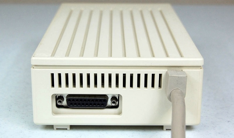
The Unidisk 3.5 is an 800K floppy drive for Apple II computers, using the Smartport protocol to communicate with the Apple II. The BMOW Floppy Emu disk emulator is also capable of emulating a Smartport disk, so in theory it should be possible to plug the Emu into the Unidisk’s daisy chain port, and use them both together. Unfortunately it doesn’t work, for reasons that weren’t clear until recently. The good news is I now understand what’s going on, but the bad news is it’s probably impossible to make it work without hardware modifications.
Smartport is a bus-based protocol. Each disk is assigned a unique address at startup, and it should only respond to commands for that address. The original Floppy Emu firmware for Smartport was intelligent enough to do that, but it contained some implicit assumptions that were wrong in a daisy chain situation with multiple Smartport drives present. Fixing those was the first task. For example, it would ACK the receipt of any Smartport command, even if it didn’t actually respond to it because it was for the Unidisk. It would also enable its output on the READ and HANDSHAKE lines whenever any Smartport drive was enabled, interfering with the Unidisk.
Address Assignment
After resolving those problems, daisy chaining still didn’t work. The logic analyzer showed that the Floppy Emu was never even assigned a Smartport address. Here’s the telltale trace:
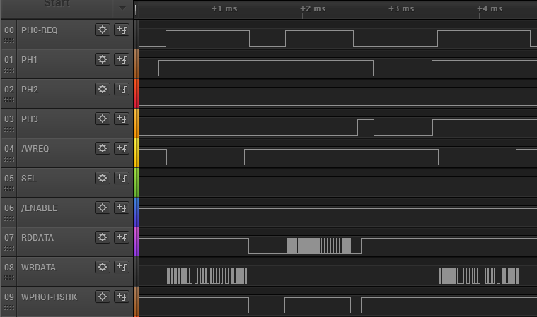
The first set of squiggles there on WRDATA (channel 08) is the computer assigning address 1 to the Unidisk with an init command. The following squiggles on RDDATA (channel 07) are the Unidisk’s reply, which is “OK, and there are no more Smartport devices after me”. The next command on WRDATA is a request to read sector 0 from the Unidisk, so Floppy Emu was completely ignored.
Determining what those squiggles mean is a tedious process. I have to zoom in until I can see each positive and negative transition of WRDATA. Every 4 microseconds there will either be a transition (a logical 1 bit) or there won’t be any transition (a logical 0 bit). I have to write down the bit sequences, frame them properly into bytes, and then consult the Smartport spec to make sense of it all. Maybe someday I’ll write an automated tool to do all this, which would make the debugging process dramatically faster. For now I’m happy simply to graph all the signals, because there was a time when I didn’t have even that much.
So why doesn’t the Floppy Emu get assigned a Smartport address? If I were designing the Smartport protocol, I would probably have it send as many init commands as necessary to give addresses to all the drives. Just keep sending init commands, incrementing the address each time, until all drives have received an address and no more init responses are received. But Apple chose a different solution, where each Smartport device is expected to know definitively whether or not there are more Smartport devices behind it in the daisy chain.
Input Becomes Output
Apple used a sneaky trick to accomplish this. On the DB-19 connector, pin 16 is normally an input to the disk called HDSEL, which is used to control non-Unidisk 3.5 inch drives. But on the Unidisk 3.5 (and presumably other Smartport devices) pin 16 of the male connector is tied internally to ground. On the Unidisk’s daisy chain output connector, pin 16 has a 2Kohm pull-up resistor to 5V. Internal logic senses whether pin 16 on the daisy chain connector is low (another Unidisk or Smartport device is daisy chained, and its internal ground connection pulled pin 16 low) or high (no Smartport device).
Turning a disk input into a direct ground connection is dangerous. It means that if the computer tries to drive a high value on HDSEL, and a Unidisk 3.5 is connected, it will create a power to ground short and likely fry the disk controller. This will happen for certain if a Unidisk 3.5 is connected to a Macintosh. The Apple IIc and the Liron disk controller don’t connect anything to HDSEL, so they’re safe. The Apple IIgs does make use of HDSEL, but its schematics reveal a 470 ohm inline resistor to protect against a power to ground short. I’m not sure about other disk controllers like the Apple 5.25 controller or the Duo Disk controller. The Disk II controller has an incompatible 20-pin connector, but if you used the Floppy Emu’s adapter cable to connect a Unidisk 3.5 to a Disk II controller, it would directly connect +5V to ground. Ouch!
This kind of I/O switcheroo seems like a very bad idea to me. Ideally, you could plug any kind of 19-pin Apple drive connector into any kind of 19-pin controller, and the worst that would happen is it wouldn’t work. But Apple created a situation where you can actually destroy your equipment by doing this. It’s not the first time, either. Pin 4 was similarly repurposed, from a ground connection on Unidisk 5.25 and Unidisk 3.5, to a drive input signal on the Apple 3.5 drive. And pin 10 is a drive input for Macintosh and Lisa, but an output for Apple II drives.
An Unintended Voltage Divider
The Floppy Emu’s CPLD can be reconfigured to treat pin 16 as an output when in Smartport mode, with an output value of zero, to simulate a ground connection. Setting aside the potential for damage this presents to a Macintosh connection, it should get the Unidisk to recognize there’s another Smartport device on its daisy chain connector. Unfortunately it doesn’t work. Ironically it’s the CPLD protection resistors that were added in Floppy Emu Model B that cause the problem, by creating an unintentional voltage divider with the Unidisk’s pull-up resistor on pin 16.
All of the Model B’s CPLD inputs have a 1K series resistor to help protect against voltage spikes and static. This is fine when the inputs are actually inputs:

The CPLD input buffer draws only a few microamps of current. From V = IR, we can calculate that the voltage drop across the resistor will be a few microamps times 1K, or a few millivolts total. If the computer drives a 5V input signal, the CPLD will see something like 4.99 volts, which is fine.
Things are quite different when the input becomes an output, and that output has a relatively strong pull-up resistor:
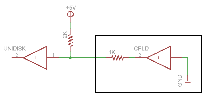
Now there’s a path through the two resistors, from 5V to ground. From the voltage divider rule, we can calculate that the voltage at the point between the two resistors will be 1.66 volts. (I measured it at 1.55 volts experimentally.) That’s far too high to be recognized as a logical zero value; 0.8 volts is the maximum valid zero voltage for 5V TTL logic. So the Unidisk doesn’t think there’s a Smartport device on its daisy chain connector, and the Floppy Emu never gets a Smartport address.
I was able to get daisy chaining working by adding a small value resistor between HDSEL and ground, external to the Floppy Emu. But that’s not much help to anybody, and it also prevents the Floppy Emu from working correctly in 3.5 inch disk emulation mode.
Solution?
So what’s the answer here? I’m afraid there probably isn’t one, and Unidisk 3.5 daisy chaining just won’t work, wah-wah and sad trombone. But maybe a reader will have a clever suggestion.
Changing the Floppy Emu’s protection resistors to something less than 1K could help. My math says a resistor of 381 ohms or less would put the pin 16 voltage at a valid logical zero for 5V TTL. By combining an old Floppy Emu Model A (no resistors) with some manually-wired external resistors, I was able to directly confirm that 1K ohm protection resistors don’t work for Unidisk daisy chaining, but 330 ohm resistors do work. But dropping from 1K to 330 ohm would be a significant reduction in the amount of protection for the CPLD. I’m also reluctant to make any changes to the Floppy Emu hardware design, which has become like a supertanker that’s difficult to change course. Any changes now would cost lots of time and money, and wouldn’t help owners of existing hardware anyway.
Another possibility is some kind of external adapter, with a physical switch for shorting pin 16 to ground. That would work, but the time needed to design, build, and stock such an adapter would be too high relative to the importance of Unidisk 3.5 daisy chaining. It’s unlikely that many people would be interested in buying such an adapter.
Read 15 comments and join the conversationLiron Support for Floppy Emu
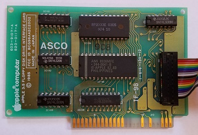
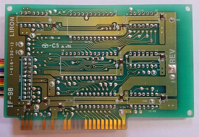
Great news for owners of the Apple II Liron disk controller card: the latest Floppy Emu disk emulator firmware adds Liron support. This means that for the first time, it’s now possible to emulate 32 MB hard disks on an Apple II+ or IIe with the Floppy Emu!
The Liron is a “smart” disk controller for the II+ and IIe, using the same Smartport protocol as the Apple IIc, IIc+, and IIgs. It was originally designed to work with the Unidisk 3.5 inch floppy drive, but other Liron-compatible third-party external hard drives were later developed. With this new firmware, the Floppy Emu is able to emulate one of these hard drives, bringing an exciting new capability to the II+ and IIe.
Smartport emulation with the Liron card works nearly identically to the IIc, IIc+, and IIgs, as described in section 10.4 of the Floppy Emu manual. Connect the Emu to the Liron card, use the Emu’s menus to select Smartport mode, and populate your SD card with up to four disk images. These will appear as four virtual hard drives connected to your II+ or IIe.
Depending on your Apple II model and its version of the autostart ROM, the Liron-connected disk may or may not automatically boot when the power is turned on. If you have an older model that doesn’t autostart the Liron, type PR#7 to get things started (or PR#N if your Liron card is in slot N).
This is new firmware, so your help with testing is appreciated. If you tried the new firmware and it worked fine, please let me know. If it didn’t work, definitely let me know. Try it in Smartport mode with the Liron of course, but also try it with the built-in Smartport of your IIc, IIc+, or IIgs to verify it still works there too, and doesn’t interfere with other types of drives that are also present in the daisy chain.
Download the new firmware here:
Floppy Emu Model A – apple-II-0.1T-F16
Floppy Emu Model B – apple-II-0.1T-F18-modelB
Floppy Emu Back in Stock

After a few weeks of scarcity, more Floppy Emu hardware is again available at the BMOW store, hot off the courier truck. It’s always my goal to keep a steady inventory available, but that’s proven more difficult than I imagined. The trouble isn’t surges in demand, or assembly problems, but just managing the supplies of all the materials involved.
To sell one Floppy Emu, I obviously need to have a main board in stock. But I also need the DB19 adapter board, which is a separate part. And I need 20-pin ribbon cables. And SD memory cards. And acrylic cases from the laser cutter. And padded mailers, boxes, bubble wrap, and postage labels. Sales grind to a halt when I run short of any of those supplies. To get them at reasonable prices requires buying them in bulk, with delivery times ranging from a few days up to two months. I can’t just drop into the corner store to buy more when I run low.
Maintaining those supplies efficiently can be challenging, and it’s not something I do very well. Real companies have automated inventory management systems that automatically order more parts as needed. I just glance into a box now and then, and maybe order more supplies if the pile looks small and I’m not busy doing something else. In this case I didn’t begin the hardware assembly process soon enough to account for the long lead time. I still had lots of hardware on hand when I reordered more, but it was all gone two weeks before the order was fulfilled. It’s one more thing I need to learn to do better.
Read 1 comment and join the conversationThe Programming Board
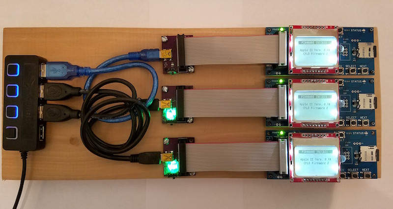
Behold the Floppy Emu programming board! Normally when you read “programming board” on this web site, you’d think of some circuitry on a PCB, but this time it’s a 3/4 inch thick plank of poplar wood. Ah, that kind of programming board!
Sometimes I need to reprogram a large number of Floppy Emus, and this tool makes the job much easier. My old method was to connect the Emus one at a time to an Apple IIgs, turn on the computer, push buttons to begin a firmware update, and then wait ~30 seconds for the update to finish. It was a slow and inconvenient process when dozens or hundreds of Emus needed reprogramming. With the programming board, I can slap down one Floppy Emu into a bracket, start the firmware update going, and then rotate to the next Floppy Emu. Everything is powered from a USB supply, and I use a hub with individual lighted switches to turn on power for each Emu bracket.
Updating three Floppy Emus in parallel is a big improvement, but there’s also another trick here that makes the process even better. With the old method on the IIgs, some fiddling with cables was necessary every time I connected or disconnected a Floppy Emu. Things would slide around on my desk, and I’d waste time getting the connectors lined up. The programming board uses metal pegs at each bracket to hold the Floppy Emu centered, so a short 4-inch ribbon cable can drop down perfectly aligned with the connector every time. Here’s a close-up of the alignment pegs:
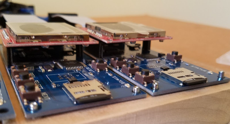
If you’re wondering about those green lights on the bottom two power adapters, they’re not status indicators, but just simple power lights. I accidentally bought some high-brightness LEDs, and even with under 10 mA current they’re so bright that it’s irritating. They’re dazzling to the point of being blinding. Fortunately the LED in the top-most power adapter didn’t work due to my lousy soldering job. I covered the bottom two with 5 layers of paper, which cuts down and diffuses the brightness enough to be tolerable.
Read 2 comments and join the conversationSnow White Case for Floppy Emu
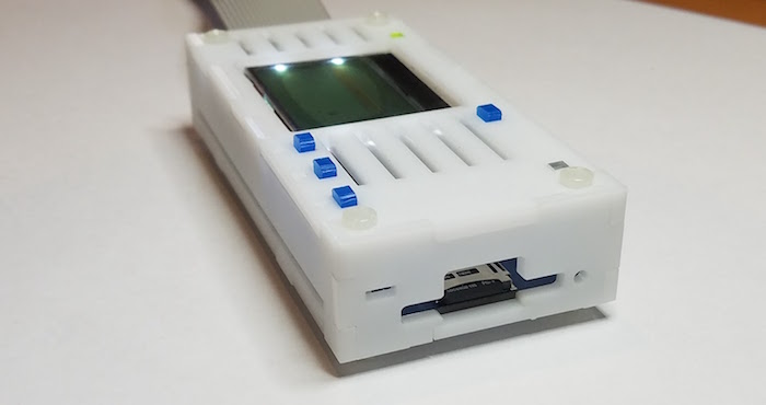
The Snow White case for Floppy Emu is back in stock. This is my personal favorite: a matte white acrylic with a slightly textured surface, following Apple’s vintage Snow White design style, and with the looks of a miniature external floppy drive. It’s available with just the case, or as part of the Floppy Emu deluxe bundle.
Be the first to comment!
