Archive for the 'Floppy Emu' Category
Floppy Emu Display Experiments
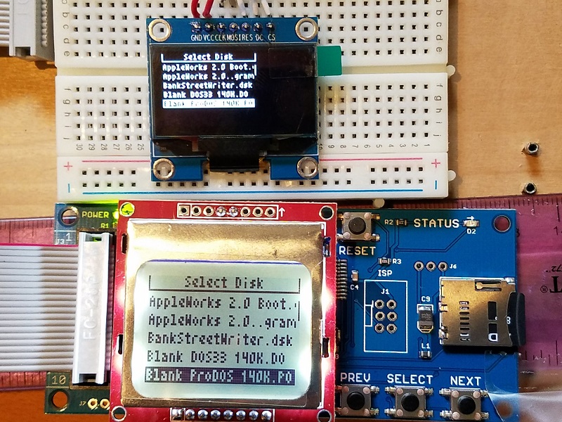
Last week I wrote about my troubles with the Nokia 5110 LCD used by Floppy Emu, with a discussion of possible replacements. There was no clearly obvious alternative, as most of the options were too big, too small, too expensive, not available from a reliable supplier, or had some other shortcoming. After some thought, I settled on the 1.3 inch OLED as the most likely alternative. And now, after hacking away on the Emu’s firmware, I have a working example of a Floppy Emu with this 1.3 inch OLED display.
Nokia 5110 Clone LCD: 1.4 inch diagonal display, mounted on a carrier PCB, 84×48 pixels, SPI interface, 1-bit graphics
No-name OLED: 1.3 inch diagonal display, mounted on a carrier PCB, 128×64 pixels, SPI interface, 1-bit graphics
The photo shows a head-to-head comparison between the old and new displays. The picture doesn’t do the OLED justice – although it looks blurry here, it’s actually very crisp and pleasant to look at. The only significant problem is the tiny pixels, which makes the text a bit difficult to read. Although the display diagonal isn’t much smaller than the Nokia LCD (1.3 inch vs 1.4 inch), the aspect ratio is different, and the OLED’s height is only 2/3 the Nokia’s height. Then the OLED packs 1.33x as many vertical pixels as the Nokia, so the OLED actually has 2x as many dots per inch. You can see in the photo, when drawn with the same number of pixels, the OLED text is only half as tall as the Nokia text. Get out your reading glasses.
It’s not too bad, and I could probably live with text this size, but it’s not ideal. It would be great if I could simply make all the text 1.33x taller to take advantage of the OLED’s extra resolution, but unfortunately it’s not that simple. Text needs to be a whole number of pixels tall, and with the Nokia LCD there are six rows of 8 pixel tall text. The most I could increase this with the OLED would be 10 pixel text, 1.25x taller, for 60 pixels total, leaving 4 pixels wasted. But 10 pixel text is an awkward number, because the OLED’s command interface is built around the concept of “pages” that are 8 pixels tall. If text spans a fractional number of pages, I’ll need to completely redo the way display updates are performed, and maintain a framebuffer of the whole display area. Unless I get really fancy (dirty rectangles anyone?), that will require re-sending all 128×64 pixels of the framebuffer to the display every time I draw anything. That will be noticeably slow, which is one of the things I wanted to avoid.
So instead of making the text taller, I’ll probably make it wider. That should help a lot with readability. With 6×8 pixel characters, I’ll get 8 rows of 21 characters each, compared to 6 rows of 21 4×8 pixel characters on the Nokia LCD. Two extra rows of text will be nice.
I still need to look at the power consumption of the OLED as compared to the Nokia LCD. When I have two Floppy Emus powered by a single 5V USB supply, the one with the OLED glitches and resets whenever I turn on the one with the Nokia LCD. I’m not sure what’s causing that, but it doesn’t happen with two Nokia LCDs.
The final hardware headache will be modifying the Floppy Emu PCB layout. In order to keep the OLED centered, I need to relocate the LCD header into a spot that’s currently packed with traces and chips. I’ll also need to move the header from the bottom section of the board to the top (unless I mount the OLED upside-down), which means running several new traces across the full height of the PCB, or just redoing the entire board layout, which doesn’t sound fun. I’ll probably want some kind of mechanical support for the bottom end of the OLED too, since the OLED only has pins along its top, and it tends to hinge downward from those pins by force of gravity. That’s not a deal-breaker, but it looks a bit unattractive.
There will be some software challenges to address as well. I can’t just replace all the Nokia 5110 code with OLED code, because then future versions of the Floppy Emu firmware won’t work on all the Emus out in the world now with Nokia LCDs. I don’t want to maintain two different versions of the firmware either, one for each display type. Ideally I’ll find a way to create a single firmware that knows how to control both types of displays, and can dynamically detect which one is present.
The OLED display costs about twice as much as the Nokia LCD, but it’ll be worth it if it eliminates the headaches I’ve had with the Nokias. Right now I don’t expect I’ll need to change the price of the Floppy Emu. I’ll see how things look once everything is finalized.
Read 7 comments and join the conversationQuest for a Decent LCD
Floppy Emu uses an 84×48 graphical LCD display. It’s just a low-resolution 1-bit display, but it’s fast and easy to use, and has a nice built-in backlight. The display is actually a clone of the old Nokia 5110 phone display, and it’s made by semi-mysterious third-party factories in Shenzhen. It can be purchased in bulk for about $2.50 apiece. Photo from RH Electronics.
The big problem with these Nokia 5110 displays is that their reliability stinks. The actual LCD module (the glass and metal bit) is clipped onto a supporting PCB with some passive electronics, and it’s only a pressure-fit holding the two together. If it’s not clipped in just right, the display will exhibit contrast problems, or glitchy behavior, or just won’t work at all. Gently pushing on the LCD frame sometimes changes the pressure-fit enough to make these problems appear and disappear. Adjusting and tightening the LCD clips, as described in the Floppy Emu manual, is the only thing I’ve found that helps.
The electronics assembler that builds Floppy Emus must go through every LCD to check for problems. They usually end up discarding about 10% of all the LCDs, because they don’t work no matter how the clips are adjusted. Once the boards are finished, I do a second check of each LCD immediately before it’s shipped to the customer. This often requires more fiddling with the clips, or manual contrast adjustments, and a further 5% of LCDs are discarded. It’s very time-consuming, but despite all this effort, some troublesome LCDs still reach customers who must then make further adjustments.
In the most recent batch of LCDs, the pressure-fit contact design changed slightly, and it now appears to be even more troublesome than before. At the same time, the LCD bezel was unexpectedly enlarged by 2mm, forcing me to redesign the Floppy Emu acrylic case to match. This is a risk of buying generic parts from eBay and Alibaba, with no manufacturer to stand behind them or datasheet to document them.
Surely There Must Be Something Better?
It would be very nice to replace the 5110 displays with something similar but more stable. A replacement would need to handle about 84 x 48 1-bit pixels (equivalent to 21 x 6 text characters), with a diagonal size about 1.5 inches, and ideally use an SPI interface. Unfortunately, I’ve found nothing that even comes close. The alternatives are either much too large/small, lack graphical capabilities, are too slow, or are much too expensive.
Character and numeric displays aren’t appropriate, since they can’t do graphics or six rows of text. So looking at Digikey’s Display Modules – LCD, OLED, Graphic category, and sorting by unit price quantity 100 purchasing, and including only those results that have at least a few hundred units in stock, I found these:
128×128 RGB LCD, 1.44 inch diagonal, $4.23 – This could almost work, except I believe it’s a 24-bit color display, so the microcontroller would need to move 24x as much data to draw on it. And because it’s a much higher resolution, the amount of data to moved must be still higher to maintain the same font sizes as the old display. And it’s a slow I2C interface, instead of fast SPI. And there’s no datasheet.
128×32 LCD, $8.01 – This is an odd shape, doesn’t have enough vertical resolution, and uses a parallel 8-bit interface.
Another 128×32 LCD, $8.69 – Also an odd shape, and not enough vertical resolution.
128×160 RGB LCD, 1.8 inch diagonal, $8.83 – This is another color, higher-resolution display like the $4.23 one, but it uses a parallel interface.
128×64 LCD, 2 inch diagonal, $9.52 – Too big, too expensive, uses a parallel interface.
Non-Branded Options
Nothing from DigiKey looks suitable. What about other options from eBay or Alibaba?
128×64 OLED, 0.96 inch diagonal, $2.91 – This could sort of work, and I have one of these modules already. But it’s tiny, smaller than a postage stamp, which isn’t really suitable. It’s also I2C which means the interface is comparatively slow. Coming from a random non-branded eBay seller, it’s also not clear it would be any more reliable than the LCD display I have now.
128×128 RGB LCD, 1.44 inch diagonal, $3.04 – This is basically the same as the $4.23 module from DigiKey. Although this one says it has an SPI interface. Maybe this is the best option from a list of not-so-great alternatives.
Read 12 comments and join the conversationFloppy Emu Back in Stock
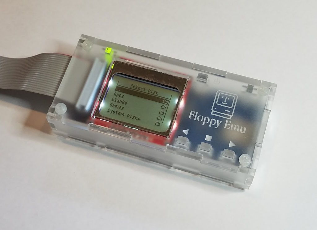
BMOW’s Floppy Emu disk emulator for vintage Apple computers is back in stock. Get yours now at the BMOW store.
Read 9 comments and join the conversationYellowstone JTAG Debugging
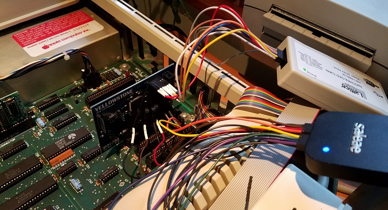
After a month of inactivity, I finally returned to my unfinished Yellowstone disk controller project to investigate the JTAG programming problems. Yellowstone is an FPGA-based disk controller card for the Apple II family, that aims to emulate a Liron disk controller or other models of vintage disk controller. It’s still a work in progress.
Last month I discovered some JTAG problems. With the Yellowstone card naked on my desk, and powered from an external 5V supply, JTAG programming works fine. I can program the FPGA to blink an on-board LED. And when I insert the already-programmed card into my Apple IIe and power it from the slot, it works – the LED blinks. But if I try to do JTAG programming while the card is inserted in the IIe, it always fails with a communication error. I’ve run through several theories why:
- It might be some kind of noise or poor signal integrity on the JTAG traces. But the traces are quite short and don’t cross any other signal traces that might carry interfering signals.
- Maybe I have power problems, and the IIe’s 5V supply is drooping briefly when I try to program the FPGA via JTAG. But I measured the 5V and 3.3V supply voltages during JTAG programming, and they look fine.
- There might be a ground loop, due to the Apple IIe and JTAG programming having different ground potentials. But I measured the difference in grounds, and it’s only 4.3 millivolts.
To help solve this mystery, I used the analog mode of my Saleae Pro 8 Logic analyzer. In analog mode, it functions like a simple 8-channel 12.5 Ms/sec oscilloscope. I recorded the 3.3V supply for the FPGA, as well as all the JTAG signals. First, here’s what the first three seconds of JTAG traffic look like when programmed externally:
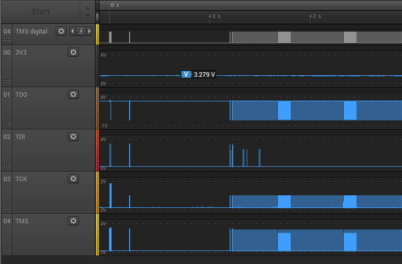
There’s about 1 second of preamble communication, and the rest is the FPGA configuration data arriving at high speed. The 3.3V supply for the FPGA remains at about 3.28V through the whole process. The JTAG signals TMS, TDI, and TDO span the voltage range from 0.17V to 3.2V, which seems fine. But the the TCK signal never goes higher than 1.86V. Uh oh, what’s happening there? Let’s zoom in a little:
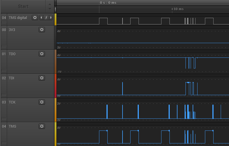
Zooming in, things are even worse than they appeared initially. TCK never climbs above 1.86V, but many TCK pulses only get half that high, stopping at 0.97V. TMS and TDI show some runts too. Zooming in even further on one of the problem areas:
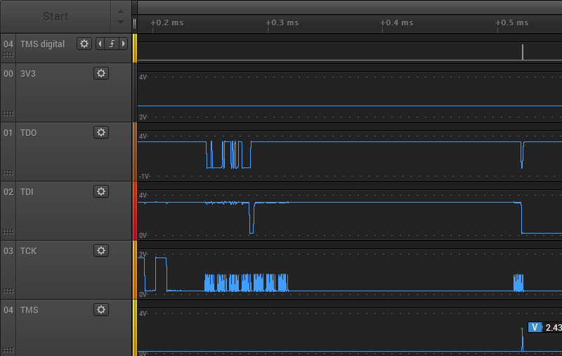
Here you can see a couple of the 1.86V TCK pulses, followed by a whole mess of the runtier 0.97V pulses. Ugh. These should all be using the full range 0 to 3.3V, or something close to it. With a clock signal this bad, it’s amazing the JTAG programming still works.
Do these graphs really reflect what’s happening? I’m a little suspicious that I’m running into limitations of the Saleae Pro 8’s analog mode. At 12.5 Ms/sec, it’s taking one analog sample every 0.08 microseconds or 80 nanoseconds. That’s pretty poor as scopes go, but the period of the JTAG clock is slow: about 1 microsecond (1 MHz operation). There should be 12.5 samples per clock period, more than enough to get a decent reading for the min and max voltage of each clock period. Therefore I think the graphs are accurate.
My conclusion is that although external JTAG program succeeds, the JTAG signals look terrible. The fact that JTAG programming fails when the card is in the Apple IIe slot likely has little to do with the IIe, and everything to do with some other basic signal quality problem.
Next I put the Yellowstone card into the Apple IIe, and repeated my test. Here’s the first three seconds of JTAG traffic again:
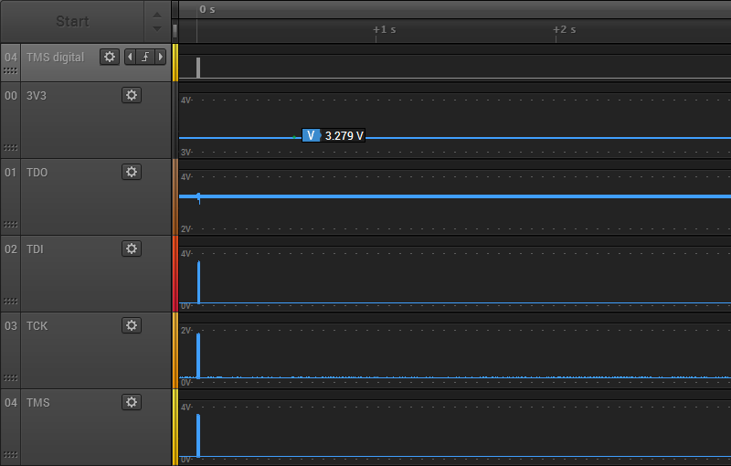
There’s a short bit of preamble communication, then nothing. Something must go wrong at the beginning, and the rest of the communication is aborted. The voltage levels all look about the same as when programming externally. The 3.3V supply is about 3.28V, TCK never goes higher than 1.86V, but the other JTAG signals use the full voltage range. Zooming in, we observe the same extra-runty TCK pulses as with external JTAG programming:
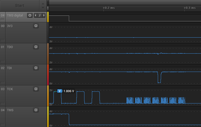
It’s not obvious to me why external JTAG programming succeeds, but programming in the Apple IIe slot fails. Both cases look equally bad. The only real difference I noticed is the TDO signal. In the case of external programming, the TDO high voltage is very steady at about 3.268 volts, and never varies by more than 0.01V. It also drops low at many points during the JTAG communication. But in the case of in-slot programming, the TDO signal is always high and the voltage is noisier. It’s a subtle difference, but you can see the minor noise here:
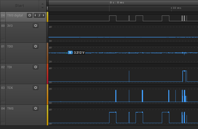
The TDO high voltage ranges from 3.187V to 3.314V, so it’s about 10x noisier than during external programming. It’s still within an acceptable range though, so maybe this isn’t important.
Finding the Culprit
Now that I know I have poor quality JTAG signals, where do I look for the cause? Poor quality JTAG programmer? Bad PCB design? Here’s a section of the PCB, showing the path of the JTAG signals from the connector to the FPGA:
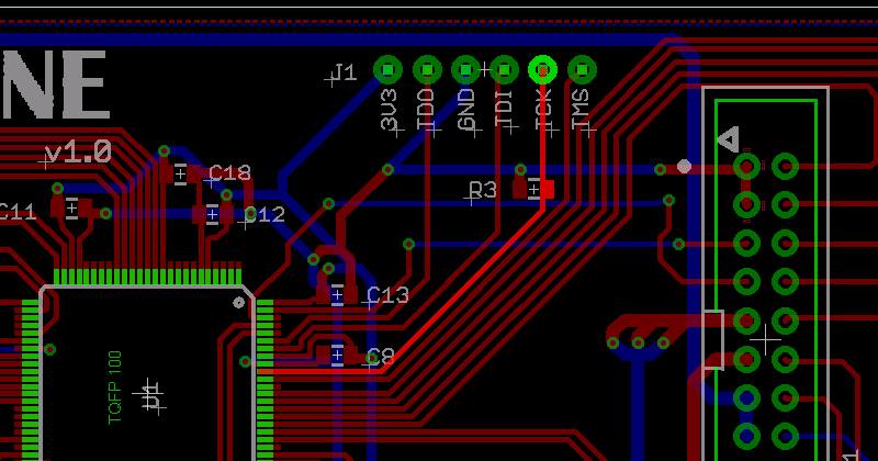
There’s not much opportunity for interference. The only PCB tracks that are crossed by the JTAG signals are voltage supplies and the disk I/O signals, which were unconnected during this test.
The prime suspect is R3, a 4.7K pulldown resistor on TCK. This was recommended by Lattice, as a precaution to prevent spurious TCK pulses causing unwanted JTAG activity when no JTAG programmer is present. Lattice technote TN1208 for the MachXO2 family says on page 12-2 “TCK: Recommended 4.7kOhm pull down.” The other JTAG signals discussed here all have internal pull-ups. 4.7K isn’t much, but maybe the JTAG programmer has an anemic drive strength and is unable to drive TCK fully to 3.3V with the pulldown present? I could try removing R3, but that wouldn’t explain why there are also some runt pulses seen on TMS and TDI. I double-checked to confirm I didn’t accidentally use the wrong value resistor for R3, but no: it’s 4.7K as intended. I also measured the resistance between TCK and GND, to see if there’s some other unintended low-resistance path to GND that’s screwing up everything, but it measured 4.7K exactly.
Read 31 comments and join the conversationFPGA-Based Disk Controller for Apple II
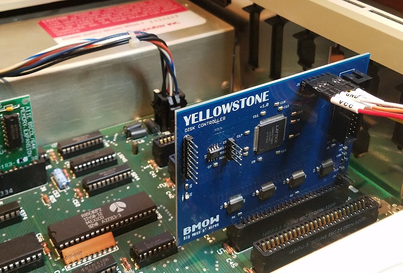
Apple II disk controller cards are weird, there are a crazy number of different types, and many are rare and expensive. Can an FPGA-based solution save the day for retro collectors? You bet! Nearly all the existing disk controllers connect the same 8-bit bus to the same 19-pin disk interface, so a universal clone is merely a question of replacing the vintage 80s guts of the card with a modern reprogrammable FPGA. This hypothetical universal controller card could connect to almost any Apple II disk drive, or a Floppy Emu. Here’s my first attempt.
An Idea Takes Root
This project has been nearly finished since August, but I’d hoped to delay announcing it until it was 100% done. Back in July there was a surge of interest in the Liron disk controller, when I updated the Floppy Emu firmware to add Liron support. For the first time, it was now possible to emulate a 32 MB Smartport disk on an Apple II, II+, or IIe with the Floppy Emu. But only Liron card owners could benefit, and the Liron card is fairly obscure and difficult to find. People started asking about the possibility of a Liron clone card, so I went to work.
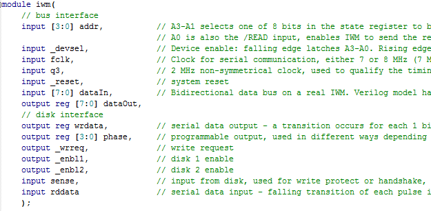
Mapping out the complete schematic of the Liron took a couple of days. It’s a single IWM (the famous Integrated Wozniak Machine), combined with a small number of standard 7400-series logic chips, and a ROM to hold the boot code. Writing Verilog code for the FPGA to duplicate the 7400 chips’ functions was easy. Creating a Verilog reimplementation of the IWM was harder, but with the aid of the IWM spec and a logic analyzer I got it done. By selecting a moderately roomy FPGA, I was able to incorporate the boot ROM functionality too, so no actual ROM chips are needed. The entire design boiled down to some 3.3V level converters and a single FPGA, with a bunch of connectors and passive components. I realized the design wasn’t limited to being a Liron clone, but could also probably be a Disk 5.25 or Disk 3.5 controller with just a change of firmware. Maybe even a UDC controller. Ooh, the possibilities!
Hardware
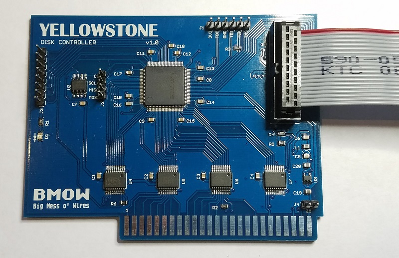
I worked like mad to finish the design in late July, just before a trip to Yellowstone National Park, which gave this project its codename. The core of the prototype board is a Lattice MachXO2 FPGA, specifically the LCMXO2-1200HC. This 100-pin bad boy has 1280 LUTs for implementing logic, and 8 KB of embedded block RAM to serve as the boot ROM or for other functions. It also has some nice features like a built-in PLL oscillator and integrated programmable pull-up and pull-down resistors. Unlike some FPGAs, the MachXO2 family also has built-in flash memory to store the FPGA configuration, so it doesn’t need to be reloaded from an external source at power-up. The FPGA can be programmed through a JTAG header on the card.
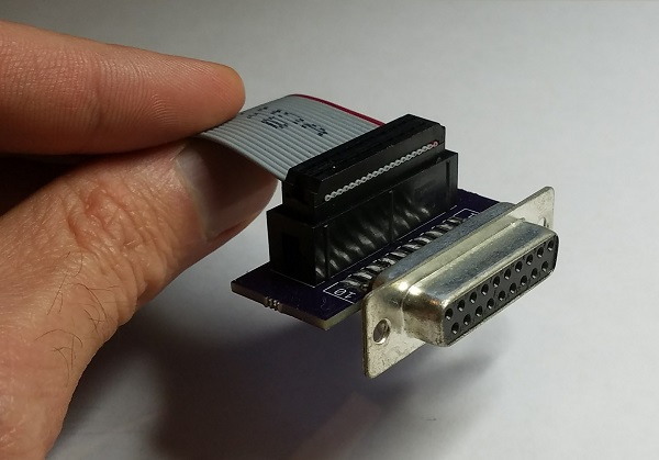
The external disk is connected to the card with a standard 20-pin ribbon cable, just like what you’d find inside an Apple IIc, or on the Floppy Emu. In fact for the Floppy Emu, you can connect a 20-pin ribbon cable directly from the Emu to the FPGA card, with no DB-19 required. For other external disk drives, I built a small adapter that converts a short length of 20-pin ribbon cable to a DB-19 female connector.
Because the FPGA’s maximum supported I/O voltage is 3.3V, but the Apple II has a 5V bus, some level conversion is needed. I used four 74LVC245 chips as bus drivers. These chips operate at 3.3V but are fully 5V tolerant, and the Apple II happily accepts their 3.3V output as a valid logic “high”. One of the chips operates bidirectionally on the data bus, and the others handle the unidirectional address bus and control signals.
There’s a tiny 3.3V voltage regular on the board, which you can see at the lower-right at U3. It’s barely any bigger than a 0805 size SMD capacitor. Even with these small components, I was still able to solder the entire prototype board myself by hand.
Just for grins I added a 2 MB serial EEPROM to the board, which you can see at U2. 2 MB is enough to store 14 disk images of 5.25 inch disks, or a single larger disk image. It’s not central to the design, but if it works then the card could function as an all-in-one virtual disk like the CFFA3000, in addition to functioning as a disk controller for external drives. More options!
Status
Here comes the embarrassing part. After July’s spurt of activity, the PCBs and parts arrived in the mail. And then I did…. nothing. Finally in October I assembled one prototype board, stuck it in my Apple IIe, and played with it for a bit. But since that day I’ve done…. nothing. I’m struggling with some internal dilemma about the balance between a hobby and a business, and doing things because I want to or because I think I should want to. I’m hoping that by publishing this summary, I may spur myself into further action.
The prototype board works as far as I’ve tested it, but that’s not very far. I verified that I can program the FPGA via JTAG, and that it responds to address and data on the Apple II bus, but that’s about it. I haven’t yet looked at what it’s doing on the external disk interface, or tried connecting a real drive. My attention has just been focused on other things, and even though I always mean to return to this project “soon”, somehow I never do.
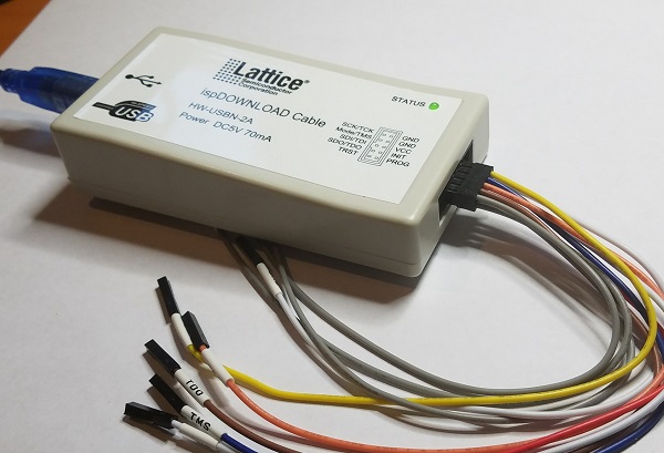
There’s at least one serious bug with JTAG programming that needs to be addressed. When the board is outside the Apple IIe and powered from a separate 5V supply, JTAG programming works fine. But when the board is actually inserted in the IIe and powered from the slot, JTAG programming doesn’t work. It always fails with a communication error. I thought this might be some kind of noise or poor signal integrity on the JTAG traces when the board is in the IIe, but the traces are quite short and don’t cross any other signal traces that might carry interfering signals. I also thought maybe I had power problems, and the IIe’s 5V supply was drooping briefly when I tried to program the FPGA via JTAG. But as far as I can tell with a logic analyzer’s analog functions, the 5V and 3.3V supplies remain stable. It’s a mystery that will require some better tools and more careful testing.
Next Steps
What’s next for this FPGA disk controller, assuming I ever finish it? Will it become a new product in the BMOW store? That was certainly my original plan, although my lack of motivation these past months has cast some doubt on that idea. I want to keep fun hobbies fun, and not have them become an obligation and a chore, which I fear is already happening with the other retro computer gizmos I’ve developed in the past few years. We’ll see how it plays out.
Assuming this eventually becomes a new product, how will users reprogram the FPGA in order to clone a different type of disk controller? It’s not reasonable to expect that everyone will own a stand-alone JTAG programmer and know how to use it. Unfortunately I can’t see any alternative solution that wouldn’t require extra hardware and complexity, and push up the cost of the board. I might add a microcontroller and an SD card socket for loading alternate firmware, but that would be a fairly ridiculous amount of extra baggage if it were used only for JTAG. Perhaps the Apple II itself could be used as a JTAG programmer, with some extra hardware that optionally bridged the data bus to the JTAG interface? Sounds complicated, and it would leave the question of how to get the firmware onto the Apple II first. Or maybe the user could choose between a few different built-in firmwares using a switch, but would be unable to load new ones? That sounds more plausible, but would mean a bug in the firmware couldn’t be easily fixed.
Fortunately those questions can wait. The first priority is to finish debugging the prototype, connect it to some real disk drives, and verify that it works. Maybe by Christmas…
Read 38 comments and join the conversationFloppy Emu and the Apple Pippin

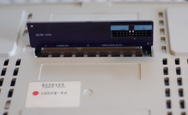
Remember the Pippin, Apple’s ill-fated attempt to enter the video game market? The hardware was effectively a modified Macintosh, running a customized version of System 7.5. The Pippin lacks any standard floppy disk connector (internal or external), but it does have a proprietary PCI-based docking connector for expansion. 20 years after its release, Pierre Dandumont has developed an adapter for the Pippin’s docking connector, making it possible to attach a Floppy Emu disk emulator. And it works!
During the Pippin’s lifetime, Apple and Bandai sold a floppy adapter for the console, and many games can use it. Pierre describes the official accessories on his blog here (French language). These accessories are very rare. Working with a colleague, Pierre made a copy of the PCB inside the official adapter, which is now available on OSH Park.
Pierre has also been busy with other floppy hacking exploits. He successfully added a Floppy Emu to a first generation Bondi Blue iMac, which famously lacks a floppy connector – it was the first Macintosh without a floppy. Apple included an unpopulated connector footprint on the motherboard, so with a little bit of soldering and the proper ROM, the iMac can have a floppy drive where it never did before.
Here’s the explanation from Pierre:
But on my blog, the Journal du Lapin (mostly in French, sorry), I like to show hacks, or curiosities. I had sent some of my tests to Steve and he offered to publish here.
The Pippin
For those who do not know the console of Apple and Bandai, it is a game console released in 1996, and very few copies were sold (about 40 000). Apple offered an optional floppy drive, which was to be placed under the console. It contains a simple PCB with a standard 20-pin connector. With a friend, we designed an adapter and then I plugged the Floppy Emu on the console. Some games allow you to save data on a floppy disk rather than on the internal flash memory (128 Kb). For example, it is possible to save images from a Dragon Ball Z game.

The iMac Bondi Blue
More amazing, the iMac. The first iMac (Bondi Blue, in 1998) did not officially have floppy drive, but Apple had left the traces of a connector on the motherboard. Obviously, the drive had been planned until a rather late date in the development of the iMac.
So I opened my iMac, soldered a 20-pin connector and connected the Floppy Emu. With the appropriate version of Mac OS, it works perfectly and it is possible to use the floppy drive with an iMac. In practice, it works with Mac OS 8.1 (the original system) and Mac OS 8.5, but not with Mac OS 8.6 or Mac OS 9 (and of course Mac OS X). Apple has actually blocked the floppy drive directly into the ROM from version 1.2. The iMac is the first Mac with a NewWorld architecture, that is, it uses a “ROM” that is loaded from the hard drive, while the previous Macintosh used a real ROM, that can not be easily updated. Since Mac OS 8.6 was delivered with a 1.4 ROM version, the floppy drive does not work with this version of the OS.
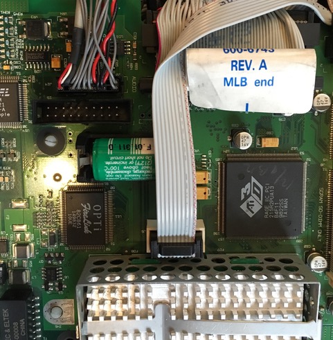
In both cases, the Floppy Emu perfectly replaces a conventional floppy disk drive and greatly simplifies testing. Thank you Steve for your work.
Great stuff!
Read 5 comments and join the conversation

