

Archive for the 'Dev Tools' Category
Reflow Soldering Still Doesn’t #*&@ Work
After four semi-failed attempts, I am not destined for success with reflow soldering using an electric hotplate. At least not with chips having a 0.5 mm pin spacing. At this point I’m only motivated to continue on by pure stubbornness, as any hope that this would “save me time” is long gone.
Building on the results of my most recent previous attempt, I tried again with a new aluminum plate and new solder paste. I was pinning my hopes on the new solder paste, after having discovered that my original solder paste syringe had already expired by the time I bought it. I suspected that the poor wetting behavior and large number of solder bridges were due to spoiled paste. Judging by its date code, the new solder paste was only five months old, and before purchase it was stored refrigerated by DigiKey to prevent spoilage. They shipped it in a cold pack, at least, so I assume it was refrigerated before that.
The results were sadly the same as my prior attempts: poor wetting and tons of solder bridges. Apparently it wasn’t my solder paste’s fault, but my technique. The video shows the story in all its gory detail.
After having more-or-less exhausted the other possibilities, I’ve come to the conclusion that using a stencil must be essential for success. Maybe no-stencil application of solder paste direct from the syringe can work for components with nice big pads, but not for chips with 0.5 mm pin spacing, unless you want to spend time afterwards manually fixing solder bridges with an iron. Lacking a stencil, I prepared a second PCB by carefully smoothing out the solder paste with a cotton swab, trying to approximate the result of a stencil. I couldn’t avoid getting solder paste between the pads, of course, but I tried to get a thin and even coating over the entire pad area. Here’s what this second attempt looked like, prior to placing the components:
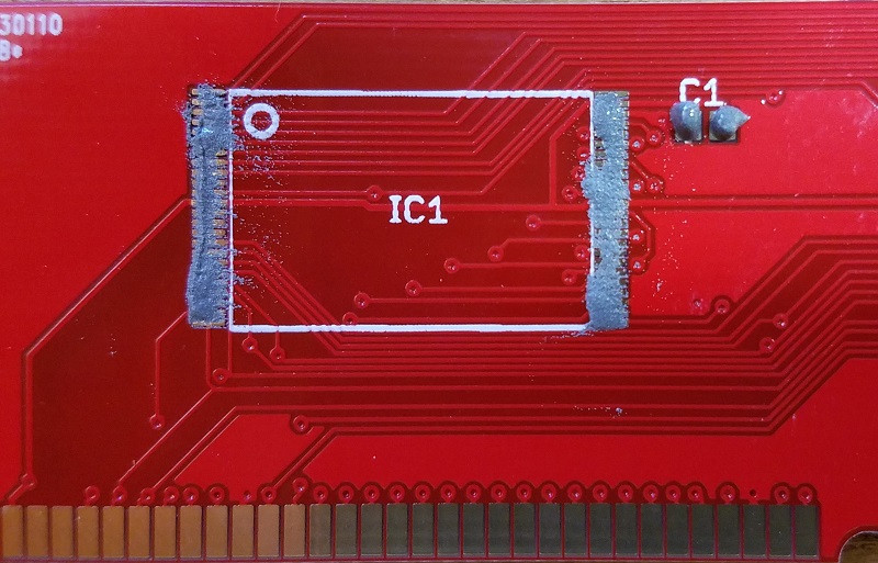
Looking at this photo now, the solder paste coating is kind of terrible, but at the time it seemed good. It’s hard to appreciate just how small those pads are, and it’s very difficult to spread the solder paste around evenly with a cotton swab.
After reflow, this second board turned out better than the first. There were fewer solder bridges, and the overall distribution of solder was more uniform. It was still far from acceptable, though.
Now it’s time for a decision. Do I order a stencil, and try again? Out of pure stubbornness and a desire to see this finally work, I want to say yes. But the practical part of my brain says no, I’ve already proven that it’s faster to assemble these boards with my current technique of drag-soldering. That makes success or failure with reflow and a stencil irrelevant. Maybe I’ll try it anyway for “educational purposes” – a sure way to justify any questionable idea.
Read 16 comments and join the conversationHot Plate + Aluminum Pie Pan = No Joy

I’m back with another episode of my DIY reflow soldering adventures! The first attempt using hot air didn’t go well, and the second attempt with a hot plate and half-inch thick aluminum block wasn’t great either. This time I used a lightweight disposable aluminum pie plate instead of the half-inch aluminum block. The idea was to reduce the thermal lag observed with the thicker block, and make it easier to remove the PCB from the hot plate after reflow was complete.
The lightweight pie plate proved to be a bad idea. Its bottom was embossed with small ridges, and was slightly warped and dented. The pie plate wouldn’t sit flat on the burner, and the PCB wouldn’t sit flat on the pie plate. To make matters worse, the pie plate also deformed as it heated. With such poor thermal contact between the burner, pie plate, and PCB, the PCB heated very slowly and unevenly. It did eventually reflow successfully after 10 minutes of heating, but I had to push down one side of the PCB with tweezers to improve the thermal contact.
The results of reflowing looked similar to my first reflow attempt using hot air: not good. There were solder bridges everywhere, but also clear evidence that many pads were dry, with only a portion of the pad area covered in solder. The photo above shows an example. The bare pads are ENIG plated and have a gold color. After reflow is finished it’s easy to see the areas that are still gold-colored, where solder never flowed. Ideally there should be no such areas.
Such poor flowing of solder makes me think the flux in my solder paste has gone bad. A few days ago I discovered that my newly-purchased paste was already beyond its shelf life, so I’ve got more solder paste on order. Hopefully that will result in better solder flow, with pads that are completely covered in solder, and few or no solder bridges.
It’s All About Time
My main goal with this whole reflow adventure is speed. I hope to assemble batches of a few dozen ROM-inator II PCBs faster than I can by drag-soldering with a standard iron. I can finish one PCB every 10 minutes with drag-soldering, and at least half of that time is consumed by fixing solder bridges. If I have to spend a similar amount of time fixing solder bridges on the reflowed PCBs as on the drag-soldered ones, then it’s unlikely reflow will provide the speed-up I’m looking for.
Even if new solder paste resolves my solder bridge problems, I’m also concerned by the setup time required to dispense the solder paste and position the chips. I timed these steps, and they took 6 minutes, all before the reflow process even started. With practice I could probably speed that up by a minute or two, but that still puts the total time including reflow close to 10 minutes, even assuming everything goes perfectly with no solder bridges. Only by reflowing multiple PCBs at once could I hope to save any appreciable time vs drag-soldering.
The video shows the entire process end to end, including dispensing the solder paste, placing the chips, reflow heating, and saying “woah” and “oh my gosh” about 20 times. I apologize for the poor quality of the video. My hand often blocks the view, and the camera isn’t positioned well to show the solder reflow in detail. Maybe you’ll find the “authentic amateur” style amusing!
Read 8 comments and join the conversationHot Plate Reflow Soldering: Round 1

Last week’s attempt at reflow soldering with hot air didn’t go very well. Today I gave it another try with an electric hot plate, and it still didn’t go well, but maybe I learned something in the process. Will the third attempt bring success?
My goal this time wasn’t really to solder anything important, but simply to test how quickly the hot plate heats up, and where on the control dial’s warm-low-medium-high scale will produce the necessary temperatures. I used an infrared thermometer to measure the surface temperature of the burner.
Part 1 – Naked Hot Plate
With nothing on it, and the dial set to “medium”, the hot plate temperature increased by about 100 degrees Celsius per minute, reaching the 183 C melting point of solder after roughly 90 seconds. From there it kept on going to 300+ C before I aborted the test, so “medium” was clearly too hot. I later found a setting just above “warm” that produced a steady temperature about 150 C, which is about right for pre-soak. Unfortunately there was a large amount of temperature variation between different areas of the burner – about 45 deg C. This could cause problems form uneven heating if a PCB were placed directly on the burner.
Part 2 – With Aluminum Heat Spreader
For my second test, I placed a 6 x 6 x 0.5 inch aluminum block on top of the burner, to use as a heat spreader. I put an old PCB on the aluminum block, with solder paste and a few small capacitors. It was quickly obvious that the aluminum block was far too thick for this purpose, with much too high a thermal inertia (what’s the right term for this?). Its temperature barely rose at all initially, but then it continued to climb for several minutes even after the hot plate was turned off, as heat was absorbed from the still-warm hot plate.
When the aluminum and PCB reached about 100 C, I decided to turn the hot plate back on to “medium” and just let it rip. The temperature rose by about 15 deg/minute, which is pretty slow. Once it reached roughly 210 C and the solder paste was nice and melted, I turned off the hot plate, but the temperature kept going up! The hot plate burner was probably still at 300+ C, and the aluminum was still slowly absorbing heat. I had to slide the PCB off the aluminum while the solder was still molten in order to allow it to cool. Not good.
The temperature variation between different areas of the aluminum was only about 5 deg C. But the temperature variation between different areas of the PCB sitting on the aluminum was as much as 90 deg C – yikes! The test PCB was very slightly bowed, resulting in some areas not actually touching the aluminum, making them much colder than other areas just an inch away. I’m not sure how to fix that. Maybe I could press down on the PCB with a non-conductive tool while it’s cooking, but that would make it difficult to use the thermometer or adjust the control dial, and would make it almost impossible to reflow more than one board at a time.
I was surprised to see how long it took the hot plate to cool off after use. More than an hour after finishing these tests, the aluminum block was still at 55 C. That could be a problem if I need to run several batches of PCBs through hot plate reflow. Will I need to wait 10, 20, 30+ minutes between batches, to allow the hot plate to cool?
What Next?
Maybe a reflow toaster would be easier than a reflow hot plate, but most of the advice I’ve heard says the opposite. I’m also very reluctant to use a toaster, since even a small toaster would be hard to fit in my work area, and it’s tough to see inside a toaster to observe what’s happening during reflow. I really like the open loop simplicity of the hot plate method, and would prefer not to mess around with toasters and thermocouples and temperature controllers unless there’s no alternative. If it comes to that, I might just give up on reflow and stick with hand soldering.
For the next test, I’ll use a much thinner aluminum plate, or maybe just a couple of sheets of aluminum foil. I think the 100 deg/minute warming I observed without the aluminum block is actually about the right rate for reaching the pre-soak temperature, if I can find the necessary control setting to pause it there for a minute afterwards. But I probably still need something to help even out the hot spots on the hot plate burner, to ensure the PCB is warmed evenly.
Read 6 comments and join the conversationReflow Soldering Fail
I’ve long wanted to try reflow soldering of surface mount components, using solder paste and hot air or a hot skillet, and I recently had an opportunity to try. Unfortunately the results were very poor, and I was left wondering what I did wrong. Compared to my normal method of drag-soldering surface mount chips with a standard iron and liberal amounts of flux, the reflow method with solder paste took more than twice as long and led to worse results overall.
My test case was the ROM-inator II SIMM, which has a couple of chips with a 0.5 mm pin spacing. With my normal soldering iron, I can tack down a few corner pins, drag solder the rest of the pins, and then use desoldering braid to clean up the inevitable solder bridges that sometimes occur between adjacent pins. It’s something of a slow and tedious method, but it works.
For this reflow experiment, I used a syringe of MG Chemicals Leaded Solder Paste. The needle on the MG syringe is quite large, and the bead of solder paste it dispenses is far too wide for detailed surface mount work. I dispensed about 0.1 mL of the solder paste into a second 1 mL syringe with a 22 gauge needle, which allowed me to create a nice narrow line of paste with very little finger pressure on the syringe’s plunger.
Solder paste has a limited shelf life, and you’re supposed to keep it refrigerated to help preserve it. I believe the flux in the solder paste evaporates more slowly at low temperatures. I made a conscious choice not to refrigerate, accepting that the paste would spoil faster than normal, because I wasn’t excited about keeping leaded solder where I keep my food. For this test, the solder paste was just one week old, and should still have been quite fresh.

I didn’t use a PCB stencil, because I didn’t have one, and because I was skeptical I could hand-position a stencil to sub-millimeter accuracy anyway. I also wasn’t excited about the mess created by squeegeeing solder paste across a stencil. Instead, following some advice from a tutorial, I used the syringe to dispense a very narrow bead of solder paste straight down the line of pads on the PCB. While it might seem that this would cause all the pins to be soldered to their neighbors instead of to the pads, the magic of flux and solder surface tension should have made it work OK.
Using tweezers, I positioned the chips on the pads, aligning them as accurately as I could. The MG solder paste had a nice amount of stickiness to it, holding each chip steadily in place after I’d positioned it. That magic surface tension of solder should have helped here too, causing the chip to “snap” into perfect alignment with the pads once the solder began to melt.
I used a hot air rework station to heat the pads, and before long the solder paste melted into a silvery and shiny color. I let it go for a few more seconds to ensure everything was fully melted, then removed the hot air and let the board cool.
Results
Despite having put down a very narrow bead of paste, many of the pins were bridged together. In this respect it was as bad or worse than my hand-soldering efforts, which was disappointing. But while some pins became bridged to their neighbors, other pins had too little solder, or looked completely dry. Overall I’d say the row of pins looked like it had too little solder rather than too much, so I don’t think the bridged pins were due to applying too large a bead of solder paste.
A second and more serious problem was the positioning of the chip. When hand soldering with an iron I can usually align those 0.5 mm pins with their pads fairly accurately, but the gray solder paste made the task more difficult this time. After dispensing the solder paste and placing the chip, but before melting the solder, the row of pins looked like a silver and gray blur. It was very tough to see if it was positioned accurately. The result was that two of my chips were positioned with the pins misaligned far enough from the pads to create a mess I was never able to fix. It only takes about 0.2 mm of misalignment to create a major problem with pins this closely spaced.
Even when the chips were aligned properly, I still had to go back and forth over each row of pins with the iron and flux, to fix the solder bridges and flow more solder onto pads that had too little. In effect, I had to drag solder the chip after having already reflow soldered it. Definitely not an improvement over the old method.
I built four ROM-inator II SIMMS this way, refining my technique each time in the hopes that the results would improve, but they never really did. Two of the four SIMMs couldn’t be salvaged, and had to be scrapped.
The title photo above shows one of those reject SIMMs, with a poorly aligned chip, after I’d made about 50 passes with an iron, flux, and desoldering braid trying to clean it up. It’s a mess, which is why I like the photo, but don’t take the photo as being a literal example of the results immediately after reflowing. I should have thought to take some photos after the reflow process, but before I’d touched any pins with an iron. It looked much cleaner and nicer then, but was misaligned and had many solder bridges and many pads with low or no visible solder.
Explanation
Why did this work so poorly? I don’t think it was the absence of a stencil. Attempting to position the chip smeared the solder paste around, so even if I’d had a stencil and used it perfectly, I still would have had smeared paste between the pads anyway.
I also don’t think my hand-dispensed solder paste bead was the problem. Using the 1 mL syringe, I was able to dispense a nice and even bead that was about as wide as a single pad, roughly 0.3 mm or so. Given the occasional low- and no-solder pads I observed, I probably had too little solder if anything, not too much.
Maybe 0.5 mm spaced pins are simply too small and close to be reflow soldered using this method? For comparison, I used the same reflow method to solder some 0805 sized SMD capacitors on this PCB, and it worked perfectly every time. No doubt larger sized components are easier to solder correctly, but I’m dubious that 0.5 mm pin spacing is beyond some threshold that can’t be reflow soldered using this method.
Maybe the temperature profile during reflow was far enough off to cause major problems? A real reflow process in a commercial oven would have a preheat phase about 4 minutes long, then an actual reflow time (above the solder’s melting point) of 60-90 seconds. My hot air method was much faster than that: point the hot air tool at the pads, wait maybe ~30 seconds for the solder paste to melt, wait another ~10 seconds to make sure it’s completely melted and reflowed everywhere, then remove the hot air.
Maybe the solder paste had already gone bad after a week at room temperature. That seems hard to believe, but it would explain the apparently poor wetting that I observed, with frequent solder bridges at the same time as other pins were dry, and the failure of the chip to snap into the proper alignment when the solder melted. The MG Chemicals syringe doesn’t have a date on it, but it’s marked with lot code 15-349 and was purchased new last week. If 15-349 means it was made in 2015 (on the 349th day perhaps), and the syringe has been stored at room temperature in an Amazon warehouse since then, that would certainly be a problem.
Maybe the way I heated the pads with the hot air gun caused a problem? This seems plausible. The heat was localized to a small area, so I would reflow the pins on one side of the chip, then reflow the other side 20 seconds later. Perhaps if the entire PCB had reached reflow temperature at the same time, using an oven or skillet, I might have had better results.
Any other good theories?
Read 12 comments and join the conversationSaleae Pro 8 Logic Analyzer Review

When Saleae’s first USB-based logic analyzer burst onto the electronics scene in 2008, it was praised for its ease of use and low cost. For 2014 the company revamped its product line, replacing all its existing models with four new products. Last month the nice folks at Saleae were kind enough to send me a new Logic Pro 8 for review, so I recently had a chance to test the hardware first-hand. In brief, it’s well-polished and good at what it does, though I wish it did more.
But first – what’s a logic analyzer? Much like an oscilloscope, an LA is a tool for examining electrical waveforms in a running circuit – the so-called “device under test” or DUT. But where an oscilloscope is used to view analog waveforms with a continuously varying voltage, a logic analyzer displays digital waveforms whose value is either 0 or 1. Most oscilloscopes have two channels, but typical LAs have at least eight channels, and sometimes 40 or more. An LA also includes powerful software for triggering, decoding, and dissecting the collected data. If you do any kind of digital electronics work, a logic analyzer is indispensable.
In the old days, an LA was a stand-alone tool, like my ancient HP 1631D. Modern LAs such as Saleae’s are more likely to be PC peripherals consisting only of the signal acquisition hardware, with all the display and analysis work handled by a software program on the PC.
Specs
The Logic Pro 8 is the second from the top in Saleae’s product lineup, which also includes the Logic 4, Logic 8, and Logic Pro 16. Priced at $399, it’s an 8 channel logic analyzer with a max sampling rate of 500 Megasamples/sec, though when using all 8 channels the max sampling rate is reduced to 100 MS/sec. The Logic Pro 8 uses USB 3.0 to push all that sample data to the PC at high speed.
Saleae recommends a minimum of 4x oversampling when capturing digital signals, so 100 MS/sec is enough to reliably capture data from digital systems with signal speeds up to 25 MHz. With four or fewer channels in use, the full sampling rate of 500 MS/sec is possible, allowing capture of digital signals up to 125 MHz. It’s important to remember that these are signal speeds, not CPU core speeds. The Beaglebone Black may have a 1 GHz processor, but its GPIO signals will normally be changing state at a few tens of megahertz at most. I’ve personally never built a digital system with external signal speeds above 5 MHz. 100 MS/sec will be more than enough for most hobbyist purposes.

Unique among the competition, all the new Saleae models except the Logic 4 feature input channels with dual digital/analog capability. Each channel can be configured as a digital input, an analog input, or both simultaneously. The analog sample rate is limited to 50 MS/sec with up to three channels, with a bandwidth of only 5 MHz, so it’s not going to replace a bench oscilloscope. But as a quick sanity check for what’s happening in the analog domain for low-speed signals, it’s a nice addition.
Unlike some other logic analyzers that feature external clock and trigger inputs, 8 channels on the Logic Pro 8 means 8 total inputs. There’s no support for external clocking, which is a disappointment. None of the current Saleae LA models have external clock inputs, and they’re the only logic analyzers on the market I’m aware of that lack this feature. I hope to see an external clock and trigger added to Saleae’s future products.
The Pro 8 supports logic levels between 1.2 V and 5.5 V for digital signals, with user-selectable threshold voltages. In analog mode, the input voltage range is -10 V to +10V. Analog signals are captured at 12-bit resolution.
Sample Streaming
All of Saleae’s logic analyzers are streaming samplers, an important detail that affects how they perform. A streaming sampler is essentially the opposite of the more familiar buffered sampler design. Buffered logic analyzers contain dedicated high-speed memory for storage of signal data. Typically the memory is enough to hold a few thousand sample points, and when it’s full, signal acquisition stops. The acquired data is then displayed and analyzed as a post process.
In contrast, a streaming sampler has little or no built-in memory. Sample data is streamed over USB in real-time to the connected PC, where it’s stored in RAM or on the hard disk. This enables huge signal captures containing millions of samples, much larger than what’s possible with a buffered sampler. But when using many channels and high sample rates, streaming can overwhelm the PC’s available USB bandwidth, resulting in failures. Faster PCs and a USB 3.0 connection both help. This design explains why streaming samplers generally don’t have more than 8 or 16 channels – there just isn’t enough USB bandwidth to stream more channels in real-time.
Unboxing and Setup

The Logic Pro 8 seems impossibly small – just a two inch square aluminum puck. It comes packed with a USB cable and two flying lead wiring harnesses, containing eight signal wires and eight ground wires. The wires are terminated with a female 0.1 inch connector, which can be plugged directly onto standard male headers, or connected to one of the 16 included IC test hooks. The whole setup packs away into a cushioned nylon carrying case. It’s all quite nice, and the value of the included accessories is something to consider when comparing the Logic Pro 8 to its competition.
The Logic is so small and light, it can get lost on a desk, or pulled off the desk by the weight of the cables attached to it. This is one instance where Saleae may have too much of a good thing, and a bit of extra size and weight might be welcome.
I was slightly confused by all those ground wires at first. According to Saleae, it’s only necessary to connect one of the ground wires for most applications, but for best results with analog sampling all the ground wires should be connected.
There’s no software CD included with the Logic Pro 8, and only a small quick start card that advises readers to visit www.saleae.com for instructions and software. No matter, anything they included in the box would likely be out of date by the time it was opened anyway.
The client software runs on Windows, Mac OS X, or Linux, and downloading was easy, with no registration or other annoying hoops to jump through. I was surprised by this pop-up, though:

You must use a beta version of the client software if you have one of the current Logic models, including the Logic Pro 8. The release/stable version of the client software only supports the older, discontinued models. I’m probably reading too much into the word “beta”, and Google has conditioned us all to be comfortable with software in perpetual beta, but this strikes me as a little strange. Supplying unfinished beta software to customers who’ve paid up to $499 for Saleae’s latest and greatest hardware risks annoying those customers and spoiling goodwill. Fortunately, Saleae’s customers seem to be an understanding bunch.
Once downloaded, the client installs a Saleae USB driver as well as the actual client application. There aren’t any configuration choices to make, so the whole installation process is quick and painless. Within a few minutes of opening the box and downloading the software, everything is set up and ready to use.
Working with the Logic
For basic setups, capturing and analyzing data with the Logic Pro 8 is simple. Just connect the ground and signal wires to the device under test, hit the friendly green “start” button, and in a few moments you’ll have a screen full of waveform data. Digital and analog data are displayed on the same screen, with the same time scale. From here you can zoom in and out of the captured waveforms, or pan left and right to view different time periods. The zooming and panning is all very smooth and quick.
Viewing a group of assorted waveforms is all well and good, but the real strength of a logic analyzer comes from the “analyze” part of its name. The Saleae client software includes several built in protocol analyzers that can extract high-level data from raw waveforms. For example, the async serial protocol analyzer can reconstruct a serial byte stream from raw RS-232 data on a channel. Tell the analyzer which channel to examine, and the bit rate and parity settings, and it does the rest. The decoded serial data is displayed as an annotation overlay on the raw waveform, and also in a table view. The current version of the software contains over 20 protocol analyzers, including async serial, I2C, SPI, JTAG, MIDI, simple parallel, and many others.

Digital and analog sample rates can be adjusted independently, and the total capture length is also selectable. Unused channels can be turned off. In general, the fewer channels that are used, the higher the sampling rate that the Logic Pro 8 can achieve.
For the basic use case of grabbing some signals and eyeballing what’s happening, the Logic Pro 8 is excellent. It’s amazing how smooth and easy the whole process is, especially compared to other logic analyzers that might have similar specs. Navigating through the waveforms is a pleasure, and helpful measurement cursors pop up wherever you place the mouse pointer. It’s really a pleasure to use.
One missing feature I’d really like to see is a state mode, or state table view. With a complex system, I often find it’s easier to view things as a list of consecutive states, with one state per line, rather than as a collection of individual waveforms plotted against a time axis. The Saleae software does have a list panel showing the protocol analyzer results, but there’s not much functionality to it. When I’ve worked with other logic analyzers in the past, I spent almost all my time in the state view, and almost never looked at the waveform time view. Saleae needs to expand the existing list panel into a full-fledged data view screen, with functionality similar to the waveform view. Here’s what state view looks like on my old HP 1631D:

One minor gripe is the lack of a continuous capture mode. When you press the start button, the client software will capture one buffer’s worth of data, display it, and then stop. Sometimes it’s helpful to use a logic analyzer to do continuous capturing like an oscilloscope, many times per second, constantly updating the results on screen. If you’re capturing the same event over and over, this makes it easy to see if any event is different from the others, or if there’s timing jitter. Unfortunately the Saleae software doesn’t support continuous capturing.
I did experience some software problems during my testing, and the client lived up to its “beta” label by crashing several times. Most of these only required relaunching the client software, and submitting a crash report to Saleae. But in one instance, a crash somehow left my USB mouse and keyboard in an unresponsive state. Even though the PC was still running, I was forced to do a hard reset of my PC.
Triggers
What about more complex signal capture scenarios, requiring a trigger? Pressing a button to begin an immediate signal capture is OK if you’re confident the event of interest will be somewhere in the captured data – either because it happens repeatedly, or you can force it to happen when desired. But many times it’s necessary to define a custom trigger to begin signal capture only when a particular event happens – say a specific value appears on a bus, or a rare error condition occurs.
I was disappointed to discover the Saleae software only supports fairly rudimentary triggering. Similar to an oscilloscope, it can trigger on a rising or falling edge on one channel, optionally requiring a specific hi/low level on other channels. That’s insufficient for capturing complex or rare events. Most other logic analyzers I’ve seen support a large array of different triggering options, like triggering when a bus or serial value is or isn’t present, or is in a particular range, or a set of conditions happens N times consecutively, or logical and sequential combinations of multiple individual trigger clauses. For example, here are the trigger setup options for the Intronix LA1034 LogicPort, a Saleae competitor:

The lack of triggering options may be a result of Saleae’s streaming sampler design. The acquisition hardware is essentially just a high speed data collection port, and it may lack the necessary smarts to check for trigger conditions in real time. From reading Saleae’s support forums, it appears that triggering is actually performed in software on the PC, rather than in hardware. I would have thought that would make it easy to support complex triggering options, but apparently the software isn’t able to compute complex triggers in real time either. In fact, even simple triggers have major problems on the new Saleae hardware. According to the support forums, if any analog channels are in use, the software can’t keep up with incoming sample data while also checking for a trigger condition. It falls further and further behind, and the client’s memory use balloons until it crashes. The Saleae engineering team is working on a fix, but for now their advice is to turn off analog channels when using triggers.
The absence of robust triggering options might not be too bad if it were possible to search the acquired data for a complex trigger-type event after the fact. Instead of triggering on an error condition, you could capture 10 million sample points, and then search for the error condition in the captured data. The Saleae client software does have a basic search capability, so for example you can look for all instances where the value 0xC8 appeared on the serial port. But there’s no capability to search for multi-byte sequences, or combinations or sequences of conditions, or any of the complex trigger conditions mentioned earlier. In a pinch, the captured data can be exported to Excel, where other tools can be used to search, but that’s not a great solution if it’s something you’ll need to do regularly.
External Clocks
Earlier I mentioned that the Saleae LAs don’t have external clock inputs. Why should you care about external clocks? The first reason is speed. When using an external clock (the DUT’s own clock), 4x oversampling isn’t necessary, and it’s possible to capture digital signals all the way up to the LA’s max sample rate. A 100 MS/sec logic analyzer using an external clock can capture digital signals at speeds up to 100 MHz. Exactly one sample is taken per clock cycle, on the clock edge. Without an external clock, 4x oversampling is required, and 75% of the LA’s potential performance is effectively thrown away. In practice you might be able to get away with 2x oversampling and only pay a 50% penalty, but the cost is still too high.
The second reason that external clocks are important is correctness of the captured data. With external clocking, samples are taken exactly at the clock edge, and the values captured are those that were seen by synchronous devices at the clock edge. Without an external clock, samples will be taken some unpredictable amount of time before and after the clock edge, and the true value at the clock edge can’t be known.

Consider a system with two digital signals, A and B, and a separate clock signal. Imagine that the Logic Pro 8 is sampling these three signals four times per clock period, for 4x oversampling, at intervals shown by the green vertical lines. A has a transition shortly before the second rising clock edge, and B has a transition shortly after the edge. But when sampled by Logic and displayed in software, both A and B will appear to transition coincident with the clock edge. What were the actual values of A and B at the clock edge? We can’t tell.
To be fair, the speed penalty described here may not be an issue in most cases. The Logic is fast enough, and the digital signals are slow enough, that a 75% speed penalty isn’t fatal. Likewise the correctness problem may not be an issue in most cases either, as long as signals don’t change values too close to a clock edge, where “too close” means within one sample period. The average person using the Logic Pro 8 to debug a low-speed I2C communication stream won’t have any problems. But when pushing to higher speeds with tighter timing margins, the lack of an external clock is a real handicap.
Analog
To test the Logic Pro 8’s analog input capability, I used a microcontroller to generate a square wave at a few different frequencies, and then viewed it as both a digital and an analog signal. The Logic Pro 8 samples analog inputs at 50 MS/sec, with a 5 MHz analog bandwidth. When examining a 2.66 MHz digital square wave as an analog signal, there was a pronounced ringing and smoothing of the displayed analog waveform, and it didn’t look much like a square wave anymore. At 4 MHz, the analog waveform just looked like a sine wave.


I had initially assumed the analog inputs would be most useful for checking the signal integrity of digital signals – looking for overshoot, noise, or glitches that might cause problems. But given the very low bandwidth of the analog inputs, it’s just not possible to see useful analog domain details, even with low-speed digital signals. So scratch that idea.
What are the analog inputs good for, then? If you’re working on an audio-related project, the analog inputs are plenty fast enough to handle audio frequency analog signals. Or if you’re interfacing with an analog sensor, such as a light or force sensor or a capacitive touch sensor, the analog inputs will come in handy too. For the vast majority of projects, though, I suspect the analog inputs will go unused.
Plugins and Scripting
The Saleae client software offers two ways to extend its functionality: protocol analyzer plugins, and client scripting. Plugins are implemented as C++ shared libraries, and enable the client to be extended to support new protocols, or to add new options to existing protocols. Need decoding of NRZI serial data from a floppy disk? Add it yourself! This capability looks like it’s still a work in progress, and the support page lists a number of incompatibilities between analyzer SDK versions and client versions, and custom analyzers currently aren’t supported with the 64-bit Windows client.
The scripting API enables users to programmatically configure the client software, and trigger captures. Just open TCP socket 10429 on the client PC, and send text commands to control the running client. Because it’s a text-based protocol using a standard socket interface, the test script can be written in any language. This interface is great for using the logic analyzer as part of an automated test framework.
Saleae Logic Analyzers, Past and Present
The original 8 channel Saleae Logic was introduced in 2008, and was later followed by the Logic 16. These remained Saleae’s only LA products until 2014, when they were discontinued and replaced with four new models. The new models offer analog sampling and faster sample rates, but at higher prices than the models they replaced.
| Model | Price | Availability | Channels | Analog | Sample Rate, 3 channels |
Sample Rate, all channels |
| Logic | $149 | Discontinued | 8 | No | 24 MS/s | 24 MS/s |
| Logic 16 | $299 | Discontinued | 16 | No | 100 MS/s | 12.5 MS/s |
| Logic 4 | $99 | Available | 4 | 1 | 12 MS/s | 12 MS/s |
| Logic 8 | $199 | Available | 8 | Yes | 100 MS/s | 25 MS/s |
| Logic Pro 8 | $399 | Available | 8 | Yes | 500 MS/s | 100 MS/s |
| Logic Pro 16 | $499 | Available | 16 | Yes | 500 MS/s | 100 MS/s |
It’s not clear to me that the current Saleae models are a better value than the discontinued ones. If you don’t care much about analog capability, than the original 8-channel Logic model at $149 was probably a better deal than the current Logic 8 at $199. For people who need more channels, the Logic Pro 16 is clearly more capable than the Logic 16 that it replaced, but at a 66% higher price it’s only a good deal if you actually need those extra capabilities. For electronics hobbyists working with relatively slow parallel bus-based systems, the old Logic 16 was ideal. The Logic Pro 8 stands out somewhat awkwardly on the price/performance scale. At twice the price of the similar Logic 8, and 80% of the price of the Logic Pro 16, it’s hard to see why anyone would choose it.
If I were Saleae, I would bring back the original Logic and Logic 16 models, selling them alongside the new models. The original models are both good logic analyzers, representing different cost vs performance tradeoffs than those offered by the current models. And I would cut the price of the Logic Pro 8 to $299, to make it more competitive with the rest of the product lineup.
Competing Models
How do the Saleae logic analyzers stack up against low-cost LA solutions from other vendors? I haven’t used any of these logic analyzers directly, but I’ve experimented with the client software for each one and dug through their documentation, to get an idea of their capabilities.
USBee SX and ZX – $169 and $495
These are 24 MS/sec 8 channel streaming samplers like the original Saleae Logic. Unlike the Saleae units, the USBee LAs feature external clock and trigger inputs in addition to the 8 data channels. The USBee client software has similar features to the Saleae client, with equally weak triggering options. The software feels fairly clunky and awkward, although it does have a state view mode. As far as I can tell, the ZX is just the SX with more powerful software. My overall impression of both models is not great.
Intronix LA1034 LogicPort – $389
This is a 500 MS/sec 34 channel buffered sampler. It can also do 200 MS/sec state mode with an external clock. Unlike the Saleae LAs, the advertised 500 MS/sec isn’t for just a few channels, but is available when using all 34 channels. The sample buffer holds up to 2K samples, or more if using sample compression. That’s still puny compared to the millions of samples you get with the Saleae units, but it makes up for it with powerful triggering options, so you can capture only the specific event of interest. The software isn’t as pretty as the Saleae client, but it’s quite useable and powerful, with a nice state view mode and many other advanced capabilities. The only thing I noticed missing is a search feature, although with only 2048 samples there’s not so much to search. I’ve never heard of Intronix before, but the LA1034 is enthusiastically recommended in a couple of electronics forums.
Open Logic Sniffer – $50
The OLS is an open source hardware product, designed by the Gadget Factory and Dangerous Prototypes, and sold by Seeed Studio. It’s a buffered sampler, configurable as a 200 MS/sec 16 channel LA with 8K sample depth, or a 100 MS/sec 32 channel LA with 4K sample depth. The price is a bit misleading, since it’s just a bare circuit board sold without a case or test leads, but a complete setup can be put together for about $75. It supports external clock sources, and has fairly powerful triggering options, but lacks a state view mode. The popular “JaWi client” software is a little funky compared to the polish of Saleae’s software, but for an open source product it’s pretty good. The Achilles’ heel of the OLS is the documentation and setup. Documentation is a confusing tangle of wikis and docs and versions, scattered across three different web sites, with redundant or conflicting information, and frequent links to obsolete information. When you do find what you’re looking for, it’s hard to know if it’s authoritative or current. But for those willing to endure a product that’s rough around the edges, the OLS may be a worthwhile option.
DS Logic – $99
Begun as a Kickstarter project in 2014, the DS Logic is a 16-channel buffered sampler with a hefty 16M sample depth. It samples digital data at rates up to 400 MS/sec, or 100 MS/sec when using all 16 channels, and also includes external clock and trigger inputs. The client software is very similar to Saleae’s – they practically cloned the UI – but it adds a few extra features like advanced trigger options and continuous capture. A $299 deluxe version adds an analog oscilloscope function with 30 MHz bandwidth, and wireless data collection capability.
Conclusions

Saleae Logic Pro 8 – Likes
- Hardware quality
- Ease of setup and use
- Huge capture sizes
- Extensible client software
Saleae Logic Pro 8 – Dislikes
- No external clock input
- Low analog input bandwidth
- No state view
- Limited trigger/search options
- No continuous triggering
So does the Saleae Logic Pro 8 get BMOW’s recommendation? Not quite. It’s a nice piece of hardware with well-polished software, but it’s missing some key logic analyzer functions, and doesn’t offer enough extras compared to cheaper LA models to justify its $399 price tag. For basic electronics hobbyist use, I would instead recommend the Saleae Logic 8 at $199, or either of the two discontinued Saleae models if you can still find them. For more complex work requiring higher speeds, more channels, or non-trivial triggers, the LA1034 LogicPort, Open Logic Sniffer, and DS Logic all offer more functionality for the same price or less, although with less polished software. I’m looking forward to Saleae’s future hardware updates and especially their future software improvements, since three of my dislikes could be addressed entirely in software. We live in interesting times, and it’s exciting to see what the tool vendors will dream up next.
Read 19 comments and join the conversationEagle vs. KiCad Revisited

Four and a half years ago, I wrote a mini-review of Eagle vs. KiCad, two of the most popular software tools for hobbyists creating custom circuit boards. I concluded that while KiCad had lots of promise, it was too full of quirks and bugs to recommend, and Eagle was the better choice for most people.
This week I had an opportunity to try KiCad again. Although nothing had fundamentally changed, I found that my overall impression of the program was much more favorable. KiCad still has lots of annoying issues, but frankly so does Eagle. And with 4 1/2 years more design experience, I can now appreciate how some of what I originally saw as flaws in KiCad were actually just different design decisions, whose value I can now appreciate.
The Software
If you’re not familiar with either of these tools, Eagle is a commercial program created by the German company CadSoft, and according to Wikipedia it’s been in continuous development since 1988. There are several versions of Eagle, but the majority of hobbyists use Eagle Light. This version is free (as in beer), but is limited to a maximum board area of 100 x 80 mm, and may only be used for non-commercial purposes. There’s also a separate non-profit license available, and an inexpensive commercial light license. Eagle is presently the “standard” for open source hardware and hobby projects found on the web, although this is changing.
KiCad is a free program (as in freedom, and beer), developed by a team of volunteers, and more recently with help from CERN. Wikipedia says KiCad has been around since 1992, although I only first heard of it a few years ago. While Eagle is a single monolithic program, KiCad is a loose collection of several different cooperating programs for schematic editing, board layout, and other tasks.
This is not a debate over free software. The nice folks at CadSoft are great for offering the very capable Eagle Light for free, and I have nothing against people charging money for software, since that’s how I’ve employed myself most of my life. 🙂 My interest is solely in which tool is better for the job.
I tested KiCad build 2014-10-27 and Eagle 6.3.0, both running on Windows 7. This is an older version of Eagle, which isn’t quite fair, but the test was more about how KiCad has changed since I last looked at it.
So which tool is better for hobbyists? I’m going to score them roughly even, but each has its strengths. Most open source hardware projects come with Eagle design files, so if you’re extending an existing project the choice may already be made for you. Eagle is also more scriptable, and may have an easier transition path to professional-level EDA software. But KiCad’s user interface is more intuitive, its board layout tool has some nice extra features, and it can create boards of any size. If forced to pick a favorite, I would say KiCad just edges ahead for the win.
KiCad Gripes
In my original review, my biggest complaint with KiCad was the way footprint selection was divorced from component selection. In Eagle you can place a 555 timer in your schematic, switch to the board view, and place it. In KiCad, you can place a 555 timer in your schematic, then you need to run another tool to select which footprint to associate with it. Only then can you place the chip on the board and route its connections. To a beginner this is a turn-off, feeling confusing and cumbersome. But once you’ve been around the block a few times, you’ll appreciate the flexibility this approach offers. This is one feature that grew on me after a while.
The earlier review complained about graphical “droppies” on the screen, and unfortunately this hasn’t gotten better. In the layout tool especially, virtually every time you do anything, you’ll be left with half-redrawn garbage on the screen, broken lines, or other visual artifacts. But as annoying as this problem is, I found I quickly developed the habit to refresh the view or change the zoom level after every operation, restoring the screen to normal.
Other problems from my original review seemed at least partially fixed: flawed footprints (didn’t notice any this time), random pieces of text in French or German (still happens), rat’s nest wire drawing problems (seems OK now).
KiCad doesn’t automatically add a board outline. This confused me before, and it confused me again this time. It’s just a minor gripe, though. By making me draw my own board outline, it may even force me to think harder about exactly what shape the board should be, or defer the board outline decisions until the main components have already been placed.
Creating new libraries of schematic symbols and footprints was pretty challenging to understand the first time, and I had to search out web tutorials. The process is just as bad with Eagle, though. Once I had my new library created in KiCad, the process of copying, modifying, and creating new symbols and footprints felt substantially easier than with Eagle.
Modifying tracks that have already been placed still seems cumbersome with KiCad. Once a board gets crowded, you often need to introduce extra little bends and angles in already-placed tracks, in order to make room for new tracks. KiCad can do this, but it seemed like 90% of the time it complained about “two collinear segments”, or just moved sections of track in a way other than what I wanted. I found I had to resort to deleting the track and routing it over again more often than I’d like.
One spot where KiCad still lags is the integration between its various sub-tools. With Eagle, changes made in the schematic are automatically reflected in the board layout, and vice versa. With KiCad you have to export a netlist file from the schematic editor, and import it to the board layout editor, every time you make a change.
KiCad Likes
The more I used it, the more I appreciated KiCad’s “Google Maps” board layout view, where high zoom levels show each track and pin labeled with a signal name like a street map. Very handy.
In the last review I complained about problems with the design rule checker, the tool that verifies clearance between tracks and neighboring tracks, pads, and vias. This time I had no trouble with the design rules, because they’re automatically enforced as you route the tracks. If a particular track placement would violate a design rule, it just won’t let you put the track there. If routing worked this way before, I don’t remember it. It’s a very nice feature.
I also griped about the autorouter last time. Since then, KiCad has added integration with FreeRouting, an external Java-based autorouter. There seems to be some legal dispute surrounding FreeRouting, and the web-based version of the tool that KiCad links to no longer exists. However, I was able to download a precompiled Window executable of FreeRouting, which worked fine with the file I exported from KiCad. It successfully routed what I thought was a difficult section of board in only a few seconds, and the result was easy to import back into KiCad. The result did have a few crazy tracks that spanned half the board, but if I’d been doing that part myself manually, I probably would have given up before I ever finished it.
Final Cut
The reality is that KiCad, Eagle, or any other circuit layout tool has a fairly steep learning curve, and you’ll have to invest many hours of time learning to use it effectively. With the current version of KiCad, I believe it’s worth that investment of time. Those who are already happy with Eagle will probably find little compelling reason to switch, but for new hobbyist engineers, KiCad certainly deserves a close look.
Read 17 comments and join the conversation