Archive for the 'BMOW 1' Category
Video Bringup: Part 2
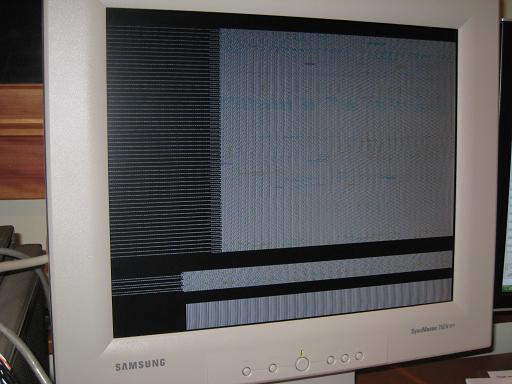
Video works! Er, sort of. After fixing the HYSNC problem, I experimented with the palette chip, just to prove it was working. With a few bytes’ worth of changes, I was able to turn everything red.
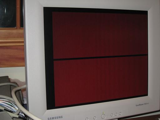
The monitor was still confused about the resolution, though, thinking it was 1152×864 when it was really 640×480. You can see in the photo above how the whole image appears twice on the screen. It should be a solid red screen.
After a little quality time with the oscilloscope, I discovered that my HSYNC fix hadn’t fixed anything at all, it had merely broken it in a different way. I reprogrammed the GAL that generates HSYNC, this time fixing the bug for real. Suddenly the monitor started showing pretty much what I expected: a screen full of garbage at 640×480. Success, of a sort.
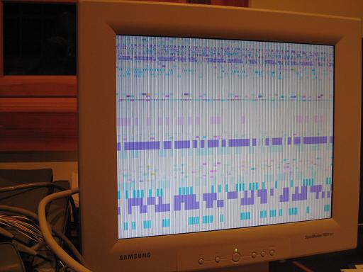
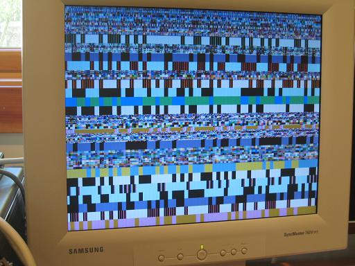
Now that things were behaving a little more sensibly, I started to worry about those light/dark vertical lines you can see in the image above. That’s not a result of the garbage data in video memory, as the lines extend straight through blocks of solid colors. It’s some kind of electrical noise creeping into the video output. It’s strange, because the lines are very “solid” and consistent, not blurry or wavy or intermittent like I would expect noise to be. I believe the 20MHz pixel clock is somehow leaking into the video output, because when I examined the VGA signal on the oscilloscope, the noise seemed to have have a 20MHz frequency. Maybe not though, because the lines aren’t just simple alternating light and dark bands, but are a repeating series of various lighter and darker vertical lines. So it seems I need some filter capacitors somewhere, or termination resistors, or a voodoo doll or something. Uh, yeah. This is basically why I’m a software guy and not an electrical engineer.
The analog VGA output is generated by a UM70C171 palette chip that I’ve mentioned several times before. I pulled it off an old video card that I dug out of the bottom of a box at Weird Stuff, a Silicon Valley warehouse of electronics junk. At the time I also bought a second old video card that had a chip made by Music Semiconductor, that I guessed was a UM70C171 clone, since its part number included the digits C171, it was the same size and shape, and the video card itself was similar. On a whim, I decided to try swapping in the Music chip, to see if it might be any more noise tolerant than the UM70C171. In retrospect, that was a little dangerous, since I really had no idea if the Music chip was some completely different IC that might fry BMOW when I swapped it in. But I threw caution to the wind, stuck in the mystery Music chip, and turned on the power. To my pleasure, not only did it work, but the noise seemed significantly reduced.
If you click the photo, you can view a larger version where the vertical noise bands are still visible. Areas that should be solid colors have thin vertical lines of varying brightness running through them. I really don’t know what causes this.
I decided to ignore the vertical lines for the moment, and set to work exercising the video modes. It’s funny, after having designed the video system, you’d think I’d know exactly what values to store where in memory to setup a particular mode or draw an image, but really I don’t. The video system schematics just prove that video is theoretically possible, but they don’t directly show you how to do it. It took me quite a while to figure out exactly where the video RAM and control registers mapped into memory, and what values to set in order make the right things happen. Honestly, I’ve only just begun to scratch the surface of it. I guess I need to write myself some documentation or a manual as I go.
Just poking bytes into memory using the monitor program, I was able to get things to happen, but I wasn’t always exactly sure what video mode I was in, or which options were currently enabled. So now I’ve reached the point where I can make things happen on the screen, but I’m not sure they’re quite what’s supposed to be happening. More time reviewing the schematics and GAL equations is needed to decipher it all. Why did I make this thing so darn complicated? I probably should have gone for a single video mode, at a fixed resolution and bit depth, and screw all this flexibility.
Nevertheless, I did get as far as clearing the screen, and turning on a single pixel in the center. I think this was in 128×480 @ 256 colors mode, but I’m not really sure. Help!
![]()
Next steps:
- Figure out what’s going on with those vertical lines, or learn to live with them.
- Reverse-engineer my own too-complicated design, so I can learn how to use it to create images.
- It seems as if the image is too dark by about 50%. What should be full white appears medium gray. I need to double-check the signal levels with the oscilloscope: they should be 0.7v for the analog VGA signals.
- Clearing the screen often causes the monitor to temporarily lose sync. Why? HSYNC and VSYNC should be unaffected by the contents of memory. Maybe some bus noise is causing false triggering of the sync signals?
- Depending on the method I use to clear the screen, it crashes BMOW. Hopefully that’s just a bug in my clear screen subroutine, and not another noise problem.
- Once all of the questions above are more or less resolved, I’ll add the character generator ROM so I can print some text.
Video Bringup: Part 1
After an eternity of procrastination and wire-wrapping, I finally finished BMOW’s video subsystem. Well, not quite finished really: the character generator is still missing, but the all the hardware is there to support the pure graphics modes. It’s about time!
With anticipation I flipped the power switch and was greeted with: nothing. The monitor turned on, which was promising, but all I saw on the screen was some faint gray noise on a black background. I spent about an hour troubleshooting, trying different video modes and palette settings, with no change. At last I realized a very stupid mistake: I’d forgotten to place all of the discrete components! The current reference, diode, and assorted resistors were still sitting neatly in a box. I put them into their places on the board, turned on power again, I saw this.
I was expecting either blackness, or some kind of static noise pattern, given that the contents of video memory were uninitialized. I wasn’t expecting this, though. Seen live, it’s even stranger than it looks in the photo. The image is flickering and dancing like crazy. It even looks as though the vertical refresh is starting at random locations within the frame, and sometimes it never gets all the way to painting the bottom of the image before it starts again at the top. Ugh. At that point I was tired and discouraged, and went to bed. Hopefully it won’t prove too difficult to resolve.
Read 3 comments and join the conversationVideo Update
I’ve been distracted by some other projects, and haven’t made as much progress on BMOW as I’d like. They were interesting distractions, at least: I worked on a crystal radio project with my daughter, and did some brainstorming about a completely new home-built computer design. I did manage to finish about 25% of the video system wiring, though, and I’m almost at the point where I can test for correct operation of the HSYNC and VSYNC signals. If I can find more time this weekend, and I don’t run out of wire, I should be able to tackle most of what’s left.
Read 4 comments and join the conversationVideo System Design
The BMOW video system design is done! Save for that one question about the correct current source setup that I mentioned previously, everything is nailed down to the last detail. I tried to cram in the maximum amount of flexibility that I possibly could, without making the hardware requirements too crazy. All told, I think I spent about a month working on the design. Now I just need to build the darn thing, and pray that it actually works!
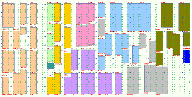
The finished design uses 14 ICs and a handful of other components, making it BMOW’s biggest subsystem. Keeping the required board area small was an important goal, since I’ve nearly filled the BMOW system board, but I’d like to leave some free space for an eventual audio subsystem. As it turned out, I used about 80% of the remaining free space for the video components, which leaves a small but non-zero area for audio. The video system components are drawn in tan, at the left side of the board layout diagram below. Click the image to see a bigger version.
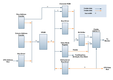
The video system supports display resolutions up to 512×480, with up to 256 colors possible at lower resolutions. A 64-column text mode is also provided, with a hardware cursor and 8×16 font glyphs stored in a character ROM. Bitmapped graphics support a variety of resolutions and color depths. Many video settings can be changed on a line-by-line basis, allowing text and graphics using different palettes and color depths to be mixed within a single screen. The following block diagram shows the major functional units. Click on the image to see a larger version.
Overview
All video data is stored in a 32K static RAM. During normal operation, 4 GALs serve as row and column counters, generating the required VRAM addresses as well as sync, blank, and other timing signals. When the CPU wishes to read or write to VRAM, the row and column counter outputs are disabled, and the CPU address is driven onto the VRAM address bus. Because there’s no explicit synchronization between the CPU and the video circuitry, the CPU may access VRAM while the video circuitry is drawing the visible portion of a line to the screen. If that happens, video noise or “snow” will appear briefly on the screen. While this video snow is undesirable, I’m hopeful that it will be tolerable in practice. The snow can also be avoided entirely, by constraining the CPU access through software so that it only occurs during the vertical blank period, when nothing is being drawn to the screen.
In graphics modes, the VRAM data is passed directly to the bit shifter without translation. Text mode operates differently, however. Text VRAM data is used as the address to the character ROM, along with the lowest 4 bits of the row count, to select the right portion of the font glyph to display. The selected portion of the font glyph is then passed to the bit shifter. Seven bits of VRAM data are used to select the character, providing for 128 different characters. The eighth bit is passed to the bit shifter as an “inverse” flag, so any character can be made to appear inverted by changing a single bit in VRAM. This can be used to indicate the cursor position, or to highlight a region of text.
In some video modes, the first byte of row data defines mode settings for that line on the screen. The character ROM can be turned on and off, palette selections can be changed, and color depth can be modified, all within different portions of the same screen. For example, a game might set up a screen that’s predominantly in 16 color mode. But it might set one palette of 16 colors for the upper half of the screen, another palette of 16 colors for the lower half, a small area of 256 colors along the top border for a status display, and a row of text along the bottom border for the score. For those modes that use it, the mode settings are latched directly from VRAM into the VIDMODE register at the beginning of each line. For the other modes, VIDMODE is latched once per frame, during the non-visible portion of the frame.
Once data reaches the bit shifter, it’s shifted out at a rate dependent on the current color depth, and passed on to the palette chip. For 2, 4, and 16 color modes, the bit shifter provides four bits of the palette data, and the VIDMODE register provides the other four. In effect, using VIDMODE allows for an additional four bits of data per pixel, but those four bits are shared by every pixel on the same line. In 256 color mode, the bit shifter provides all eight bits of the palette data, and the VIDMODE output is disabled.
The video circuitry uses the UM70C171 palette chip that I’ve mentioned several times before. It combines a 256-entry palette RAM and three D-to-A converters into a single chip. A similar result could be achieved by using a standard SRAM for the palette and three separate DACs, but at the cost of increased complexity and required chip count.
Video Modes
Four bits of control data govern the basic video resolution settings: two for the vertical resolution, and two for the horizontal. Decreasing the horizontal resolution increases the color depth, so that the number of data bytes per line remains constant, with some exceptions. Some modes use the first byte or two of row data for mode settings, with a consequent reduction in horizontal resolution. The character ROM may be turned on in any mode, but will only produce recognizable characters in 2 color mode. In the other modes, the font glyphs will effectively become small colored bitmaps, which might permit for some interesting effects. The 16 primary video modes are:
| 0 | 504×200 @ 2 colors | mode byte per line, 63×25 text with character ROM |
| 1 | 504×200 @ 4 colors | mode byte per line |
| 2 | 252×200 @ 16 colors | mode byte per line |
| 3 | 126×200 @ 256 colors | mode byte per line |
| 4 | 512×240 @ 2 colors | 64×30 text with character ROM |
| 5 | 512×240 @ 4 colors | |
| 6 | 256×240 @ 16 colors | |
| 7 | 128×240 @ 256 colors | |
| 8 | 504×400 @ 2 colors | mode byte per line |
| 9 | 252×400 @ 4 colors | mode byte per line |
| 10 | 126×400 @ 16 colors | mode byte per line |
| 11 | 63×400 @ 256 colors | mode byte per line |
| 12 | 512×480 @ 2 colors | |
| 13 | 256×480 @ 4 colors | |
| 14 | 128×480 @ 16 colors | |
| 15 | 64×480 @ 256 colors |
It looks like a pretty random assortment of resolutions and colors, but they all fall directly from the use of the resolution control bits. A few notes:
- Check out mode 12, at 512×480! That’s a lot of resolution.
- Mode 7 is probably best for displaying digital photos or smooth color gradients.
- Mode 2 at 252×200 and mode 8 at 504×400 have the pixels that are closest to being square.
- The 200 and 400 line modes are handy for adjusting the pixel aspect ratio. Otherwise the higher resolutions of the 240 and 480 line modes are probably more useful.
For applications where there’s lots of animation happening, significant amounts of VRAM data may need to be modified by the CPU each frame. If this becomes prohibitive, a bit in the VIDMODE register can be set to enable line-doubling mode. In this mode, the least significant bit of the row count is masked out, so that only data for the even rows is read from VRAM, and the same line is repeated for odd rows. This cuts in half the amount of data that must be modified by the CPU, and enables reducing the vertical resolution to as low as 100.
For the curious, I’ve posted the complete schematic diagrams and GAL equations for the video circuitry. Find a bug, or suggest an improvement!
Food for Thought
A few things didn’t work out as I’d hoped with the design. The idea of changing the video settings line-by-line is cool, but it complicated matters quite a bit, and I never did manage to iron it all out perfectly. I think that modes 9, 10, and 11 will use the mode byte correctly, but will also display it as a visible pixel. Oops.
One tricky wrinkle I didn’t anticipate is that some modes involve different byte rates than others. For 512 horizontal pixels at 1 bit-per-pixel (2 colors), a new byte must be loaded from VRAM every 8 pixels. But for all other modes, a new byte must be loaded every 4 pixels. That means that the pipeline delay is different, so the time between column count zero and the first visible pixel of the line appearing on screen is different. If combining 1-bit lines with 2, 4, or 8-bit lines in the same screen, the lines will start 4-pixels apart horizontally, so the left and right screen edges will look ragged. What’s worse, I can’t even generate the correct timing signals to make ragged lines, since I’ve run out of space in all the programmable GALs. I discovered this only at the 11th hour. My work-around is to use the same timing signals for all lines, regardless of color depth. This suppresses the first pixel of 2, 4, and 8-bit lines, and tacks it on to the end of the line instead. I can compensate for this wrap-around behavior in software, but it’s a pain.
Read 4 comments and join the conversationCurrent Source Confusion
I’m about ready to call the BMOW video system design officially complete, and hopefully I’ll be posting specs soon. I’ve run into one last snag, however. The UM70C171 palette chip requires a reference current to calibrate the DAC output. The official datasheet shows a few examples of how to do this, and I’m following the example that uses a LM334 current source in a temperature-compensated configuration shown on page 3-109. Their formula for how to choose the resistor values to get the desired current doesn’t seem to make sense, though, and doesn’t agree with the LM334 datasheet. Anyone see where I might be misinterpreting things? John Honniball mentioned that he had a copy of the IMS G171 datasheet, which should be pin-compatible. Does it say anything different?
The UM70C171 datasheet says I need a 4.44mA reference current for a singly-terminated output, and that the relationship of the resistor R1 to the current is IREF = 33.85mV / R1. Solving for R1 yields about 7.5 ohms, which is the value they show in the accompanying diagram. Also shown in the diagram is a second R2 resistor with a value of 75 ohms, which isn’t mentioned in the text.
In contrast, the LM334 datasheet on page 5 shows an example of using it in the same temperature-compensated configuration, with different results. It says the ratio of R2 to R1 should be 10:1, and IREF = 0.134V / R1. Solving for R1 yields R1 = about 30 ohms and R2 = 300 ohms. That’s a substantial difference from what the UM70C171 datasheet says.
The coefficient in the formula from the LM334 datasheet is almost precisely 4 times the coefficient from the UM70C171 datasheet, which I’m sure is significant somehow. I feel like I must be missing something obvious.
Read 5 comments and join the conversationDecisions, Decisions
I honestly cannot make up my find about whether to use this salvaged UM70C171 VGA palette chip as part of my video system design. I’ve changed my mind four times already in the past couple of days. I think I’m going crazy!
Previously I thought there would be a tradeoff for using the palette chip, and I’d need to give up some flexibility in supported bit depths and palette switching to use the chip, as compared with my original design that didn’t use it. But I’ve since worked out a few improvements to the design that avoid needing to give up anything.
From a technical standpoint, then, using the palette chip has nothing but advantages. It combines an 18-bit dual-port palette RAM and all the required D-to-A conversion hardware into a single chip.
- The required board space for the video system would be reduced by the equivalent of about 3 chips. That’s not a huge amount, but it would make a big difference in how much audio circuitry I could fit on the board, plus any other 11th hour things I’ve forgotten.
- The palette entries would be 18 bits, 6 bits per channel, compared with the 8 bit, 3/3/2 bits per channel of my custom-built output stage. That would produce much nicer looking colors when displaying digitized images or smooth color gradients, and it would completely sidestep the whole question of how to best map 8 bits to 256 colors that I wrote about last week.
- I’m less likely to encounter any problems related to high-frequency operation if I use the palette chip. It’s rated to run at up to 66MHz. With the custom output circuit, I’d have to be very careful to use high speed parts and account for the timing requirements everywhere.
- The D-to-A conversion would probably produce cleaner results than my custom circuit. There was a fair bit of noise in the video test circuit I built a few weeks ago, and the final circuit would probably suffer from some of the same problems. Also, the palette chip should produce nearly equal changes in brightness for equal changes in RGB values, which may not be the case for my custom DAC. I’m not even certain that my custom DAC will produce a brighter color for binary 100 than 011.
If I do use the UM70C171 palette chip, it will only replace about 25% of my original video system design. I’ll still need to build the circuits to generate the row and column addresses, video sync signals, VRAM, character ROM, and data latching. The only part that would be different is how a byte of video data, once it’s retrieved from VRAM or ROM, gets converted into analog RGB voltages for the monitor.
So why *wouldn’t* I use this palette chip? It sounds like a no brainer. The only reason is really a lingering feeling that it’s somehow “cheating”, or isn’t as interesting an accomplishment to build a video system if part of it is a purpose-built component scavenged from a VGA card. It’s the same argument that I went through with myself six months ago about whether to use GALs in BMOW’s design. Ultimately I did use GALs, and it’s worked well, and there’s no way I could have fit everything on the existing board without them. So from a practical standpoint the palette chip would be a big win. I guess I just need to swallow my pride a little, or let go of the “not invented here” attitude, and use what works.
Read 9 comments and join the conversation

