

Archive for the 'Bit Bucket' Category
Shiny New Computer Setup

Upgrading to a new computer is exciting, but can also be a pain. Last week I replaced my primary desktop computer with a new laptop, and the setup has involved some bumps in the road. Read on for my take on high DPI displays, desktop vs laptop, data and program migration, and Windows 10.
The old PC was a Mac Mini running Boot Camp with Windows 7. It worked well enough, aside from some quirks with USB 3.0 and bluetooth support under Boot Camp. But the end of Windows 7 support is on the horizon. Now felt like the right time to update to Windows 10 and get some new hardware. The new machine is an HP EliteBook x360, so I can work on BMOW projects from anywhere instead of being tied to a desk.
High DPI Displays
Windows 10 has some work to do before it can match the Mac’s easy retina display support. Many programs scale correctly under Windows 10, but many don’t. Under Mac OS, high DPI displays just work. Whether it’s in the OS’s own windows and settings programs, or in 3rd party software, I’ve only ever encountered one program that didn’t scale properly on a retina display.
The same can’t be said for Windows 10. On a high DPI display, most of the built-in Windows programs scale nicely and look crisp, but a few items like file dialog boxes look blurry. Older third party software generally doesn’t scale well. You’re left with a choice between viewing programs at 100% scale where everything is tiny, or viewing them at a higher scale where everything is blurry. You might think that at least text should always scale properly, even if program icons don’t, but I haven’t found this to be true. Depending on what software you use most often, the experience with a high DPI display under Windows 10 may actually be worse than with a standard DPI display.

Desktop vs Laptop
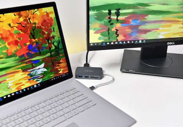
For the first time in 30 years, my primary computer is not a desktop machine. Getting the absolute fastest performance wasn’t important to me, but I thought portability would be valuable. I’m primarily using the laptop as a desktop replacement, with an external monitor, keyboard, mouse, and USB hub. But I can unplug everything and walk away with the laptop when I need to.
I hadn’t anticipated the drawbacks of using a laptop as a desktop replacement. Fewer I/O ports, limited expansion, and higher cost were all expected, but I’ve found that a laptop-as-desktop simply doesn’t work as smoothly as a desktop. Sleep doesn’t work well. Sometimes I can’t wake the computer from sleep without opening the laptop lid. Sometimes the external monitor fails to turn on after waking from sleep. The computer occasionally gets confused about applying scaling settings appropriate for the internal or external display.
And the most surprising discovery about this laptop-as-desktop? It’s loud. Louder than any other desktop or laptop I’ve ever used. On battery power the Elitebook is nice and quiet, but when plugged in, the fan roars any time CPU usage gets above 10-20%. It doesn’t take much to reach that threshold – unzipping a file, rendering a busy web page, or even a background process can start the fans going. A laptop doesn’t have anywhere near the cooling capacity of a desktop case, so the fan has to work very hard to keep the CPU cool without forcing it to throttle to lower GHz.
At lower fan speeds it’s not so bad, but at max fan speed the Elitebook is so loud that it’s nearly unusable. I can configure the power settings for energy savings instead of max performance, and then it’s quieter, but there’s a huge performance hit of 25% or more. That makes the new computer as slow as the old one it replaced.
Windows 10
I disliked Windows 8.0 so strongly that I downgraded back to 7, so I approached Windows 10 with hesitation. I’m happy to report that the experience has been mostly good. In many ways, Windows 10 just feels like a more polished version of Windows 7. The wacky paradigm-breaking elements of 8.0 are gone, including charms and the disappearing start menu and everything running full-screen. Yes, the Metro / UWP programs are still there, but Microsoft seems to have stopped pushing it so hard and UWP programs work much like any other software.
The biggest gripe about Windows 10 that I’ve heard from others is the loss of control over updates. Compared to Windows 7, there’s less ability to control the timing of Windows updates or their contents. Automatic driver updates sound scary. I haven’t been using the computer long enough to experience this yet, but I’ll watch for it.
![]()
Program Migration
Copying all your data to a new computer is easy. Copying all your programs is decidedly not easy. In most cases you can’t actually copy the programs at all, due to their extensive reliance on the registry, extra DLLs, and other semi-hidden dependencies. Attempts to copy everything from C:\Program Files will generally result in a non-working copy. Third party utilities exist for copying programs between computers, but their success rate is questionable for anything beyond basic programs.
In most cases, the only real option is to reinstall all the programs from scratch on the new computer. If you’re lucky, you can download the latest version of the program, install it, and be done. But often it’s more complex than this – you may need to create an account or get a license key before you can download or install the software. And if your current version of the software is no longer available, the latest version may not always be a good replacement. Newer versions may be incompatible with your old data or other software components. In the worst case, the software may have been discontinued with no way to download it again.
Here’s a summary of which programs were a challenge to migrate.
Easy
iTunes, Inkscape, Notepad++, GIMP, VirtualBox, Saleae Logic, Atmel Studio 7, and various small utility programs were no trouble. I just downloaded the latest versions and installed them, taking only a few minutes. All of them worked fine under Windows 10, including the drivers for the programs like Logic that use external hardware.
Medium
I couldn’t log in to Gmail with Microsoft Edge using my Yubikey for 2FA. It would always appear to succeed, but then immediately complain “something went wrong”. Attempts to use my backup 2FA methods also led to the same error. I eventually gave up on Edge and installed Chrome.
Visual Studio Express 2015 is supposedly still available, but I couldn’t find a working download link. I use VS for developing several tools like the FC8 compression/decompression utility, and an internal order-processing tool. Microsoft seems to have abandoned the Express series, but fortunately Visual Studio Community 2019 worked smoothly with my old projects.
The driver for my Zebra 2844 label printer is built into Windows, but it requires some special print setup after installing the driver. I had to contact the eBay seller who sold me the printer two years ago in order to get the instructions again. Fortunately the seller is still around and willing to help.
The latest version of Eagle (PCB layout software) is subscription based, but the last non-subscription version (Eagle 6.6) is still available and works fine.
Quicken and Lattice Diamond (FPGA software tool for Yellowstone) required an account login before I could download the software. Diamond also required generating a new license key, even though the software is free.
I purchased CorelDRAW Suite a few years ago, and have an install CD with license key. But after installing it on the new computer, I was told the license key was already in use. By me! I had to unearth the login credentials for the Corel account that I created the first time I installed the software, and use it to update the license. Fortunately I’d used my real email address when I’d first created the Corel account, instead of supplying a fake one as I often do when I’m forced to create an account for some purpose I don’t want.
Hard
MPLAB is Microchip’s software for PIC development, and I use it for ADB-USB Wombat development. Downloading and reinstalling the software was no problem, but the Wombat project had lots of errors when compiled under the new IDE. I vaguely remembered installing some other software components several years ago in order to get MPLAB working, but I couldn’t remember what. It took several hours to untangle this hairball and refresh my memory, learning that I also needed to separately install the Microchip Library for Applications, the XC32 complier, and the Legacy PLIB. Four separate installs to get a working build environment.
The standard driver for my EasyPRO EPROM programmer only supports Windows XP. There’s a newer 64-bit driver, but it’s only available on a Chinese-language web site, and it took a long time to find it. Unfortunately I couldn’t install that driver under Windows 10 because it’s not digitally signed, which is now a requirement. I found the hidden Windows setting to disable enforcement of the signed driver policy, and successfully installed the 64-bit EasyPRO driver, but the hardware still didn’t work. The device manager revealed that “the driver for this device has been blocked from starting because it is known to have problems with Windows”.
After lengthy attempts to fix this somehow, I gave up and installed a Windows 7 virtual machine for the EasyPRO software under VirtualBox. The VM is configured to allow USB pass-through for the EasyPRO hardware’s USB vid and pid.
Migrating my Perforce database was challenging. While the rest of the world has largely moved to git, I still use Perforce’s free single-user configuration for source control of my projects. The version of the Perforce server that I’d been using is no longer available for download. I installed the latest version, and directly copied over my database files, but not surprisingly that didn’t work. I followed the instructions to export my old DB and import it into the new server, but that only produced an empty database. It required many hours of slogging through the Perforce documentation to understand what I’d done wrong, and successfully export and re-import the DB into the new server.
Hardest
My experience with the Xilinx development tools was the worst. I use the Xilinx ISE to develop firmware for the XC9500 CPLD chip at the heart of the Floppy Emu, so it’s essential to my business. The current version of Xilinx’s development tool is called Vivado. Sounds fine, except Vivado doesn’t support the XC9500 chip. The XC9500 may be an older product, but it’s still being manufactured and sold by Xilinx, so it’s curious why their software doesn’t support it.
For the XC9500 you need the Xilinx ISE WebPACK, which you can still find on their site. That’s OK, except the ISE WebPACK doesn’t support Windows 10… or does it? Read the ISE 14.7 description on their web site, and tell me what it sounds like to you. Notice there are a couple of references to “VM” that aren’t explained. Also notice the warning that this version only supports the Spartan 6 FPGA, even though it’s the ISE WebPACK that provides XC9500 support. Hmm.
The ISE is a huge many-gigabyte download, but when I finally finished downloading 14.7, I discovered two things:
- The software is actually a virtual machine image containing Linux and the Linux version of the ISE.
- They weren’t kidding about it being Spartan 6 only. XC9500 is not supported.
So that’s Xilinx’s solution to providing support for their older (but still active) products? Rather than adding support to Vivado, or updating ISE WebPACK to work on Windows 10, they give you a virtual machine image and tell you to run the old software under virtualization. The web page where the software is described doesn’t even mention this.
For reasons known only to Xilinx, even this virtualized version of ISE WebPACK is limited to Spartan 6 support only. To get XC9500 support I had to go back for another many-gig download of ISE WebPACK 14.6, which doesn’t work on Windows 10 and has no virtualized version. Fortunately I’d already set up a Windows 7 VM for use with the EasyPRO programmer, so I added ISE WebPACK 14.6 to that. Now I have to do all my CPLD development in a VM, but at least it works.
All of this would be understandable if the XC9500 were an obsolete, discontinued chip. Software companies can’t maintain support for legacy products forever. But the XC9500 is still being actively sold and marketed by Xilinx. They sell a product where the required development tools don’t work on any Microsoft OS released after 2009.

Are you thinking about upgrading your computer? What’s holding you back? If you’ve recently upgraded, how was the experience? Were any software programs challenging to migrate to the new machine?
Read 15 comments and join the conversationExplaining 4K 60Hz Video Through USB-C Hub
USB-C offers exciting new capabilities, including external monitors connected through the USB port. USB-C converters to DisplayPort or HDMI are common and inexpensive. USB-C hubs with external monitor support are also common, but understanding their capabilities and limitations can be extremely confusing. Some are Mac-compatible and some aren’t. Some need driver software. Supported resolutions and refresh rates vary widely. Some are advertised as “not for gaming use”. There are mentions of alt mode and dual mode and more. Prices range from $20 to over $300 for what look like very similar features. What’s going on here?
This is the guide to high-resolution video over USB-C that I wish I’d had. If you’re hoping to connect a high-res external display to your USB-C equipped computer, read on.
October 2020 Update: see the notes at the end of this article about how DisplayPort 1.4 changes the landscape.
Forget About HDMI
Lesson 1 is to focus on DisplayPort video connections, and forget about HDMI. You’ll never find a USB-C hub that offers better video capabilities through its HDMI port than through its DisplayPort, but you will find hubs that offer better DisplayPort resolution and refresh rates. I strongly suspect most hubs with an HDMI port are actually implemented internally as a DisplayPort, with an integrated DisplayPort to HDMI converter. This is because DisplayPort video can be carried more efficiently on the USB-C connection than HDMI for the same resolution and refresh rate.
DualMode DisplayPort++ connectors are able to function as HDMI connectors with a simple passive adapter (it does 3.3V to 5V level conversion). Regular DisplayPort connectors can’t do this, and require an active HDMI adapter with more built-in smarts. Otherwise I’m not aware of any difference between these two DisplayPort types.
Bandwidth Tradeoffs – It’s All About The Lanes
The 24 pin USB-C connector is the key to understanding. The diagrams below are from techdesignforums.com.
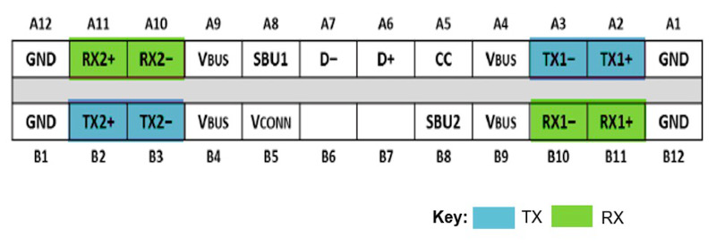
USB-C connectors have four differential pairs called “lanes” for carrying high speed data. There’s also a fifth differential pair D+ and D-, that carries old-style USB 2.0 data.
Let’s look at what happens when DisplayPort is added into the mix:
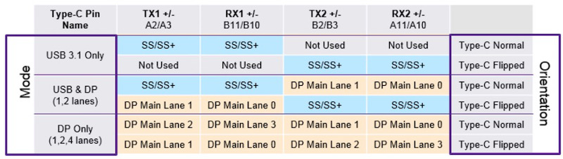
USB 3.1 Gen 2 only uses two of the four lanes, as shown in the top two rows of this table. The other two lanes are essentially wasted (they will be used by USB 3.2). These two lanes can be repurposed to carry a native DisplayPort signal, using what’s called DisplayPort Alternate Mode, as shown in the middle table rows. In this case the USB-C connector functions like a DisplayPort connector with a different shape and some extra wires for USB data. There’s no loss of USB 3.1 performance. To the computer and the external monitor, this looks exactly like a regular DisplayPort connection.
Two lanes for DisplayPort provide enough bandwidth for one external monitor at up to 4K 30Hz. That’s OK for watching movies, but a 30 Hz Windows or MacOS desktop experience is painful. To keep a 60 Hz refresh rate, you need to step down to 2K or lower resolution.
If you want 4K 60Hz, 5K, or multiple external monitors, then you’ll need to use DisplayPort Alternate Mode with all four lanes for DisplayPort data, as shown in the bottom rows of the table. To the computer and the external monitor, this still looks exactly like a regular DisplayPort connection. But now there are no lanes remaining for USB 3.1 data. There’s only the old D+/D- pair providing slower USB 2.0 data. That means any USB-C hub using this technique for 4K60 video can’t have any USB 3.1 ports on it.
External DisplayPort monitors can also be supported using zero dedicated lanes for DisplayPort Alternate Mode, with one of two approaches. If the computer’s USB-C port has Thunderbolt 3 capability, then DisplayPort data can be encapsulated within the Thunderbolt data stream. The video data becomes just one more type of packetized data multiplexed with everything else. Thunderbolt 3 has enough bandwidth to support multiple 4K60 video connections this way, with enough bandwidth remaining for USB 3.1 data too.
This is great, but Thunderbolt 3 hubs are expensive, and the computer must have Thunderbolt 3 capability, and many computers don’t. This also looks different to the computer – unlike DisplayPort Alternate Mode, there are no native DisplayPort signals and no direct connection to the computer’s GPU. It’s not clear to me whether there’s a performance penalty for treating video this way, or if it’s all handled magically by the chipset with no loss of performance. My hunch is there’s no performance penalty. If you know more, please tell me.
DisplayLink
![]()
The other method of supporting external monitors with zero dedicated lanes is DisplayLink. This technology compresses the video data on the host side, sends it over a USB 3.1 connection as generic data, and reconverts it to video on the other end using a special chip like the DL-6950. Conceptually it’s like a remote desktop connection for sharing your work computer’s screen when you’re logged in from home, except everything happens locally on your desktop.
DisplayLink is nice for squeezing high-resolution video over a lower-bandwidth connection like USB, or for supporting multiple high-res external monitors without Thunderbolt. But if you have any alternative, I think DisplayLink is best avoided. Here are some disadvantages:
- Host-side driver software is required. Driver availability and compatibility for Mac/Linux is spotty to non-existent. This is why some USB-C hubs are advertised as not Mac-compatible.
- The driver software can slow your computer. It implements a virtual graphics card performing on-the-fly compression of video data, which adds some CPU overhead.
- When the computer is very busy or there’s a lot of other USB traffic, video artifacts will appear. You’ll see pixelation, stuttering, frame dropouts, and other problems. This is why some USB-C hubs are advertised as “not for gaming use”.
USB-C hubs utilizing DisplayLink work fundamentally differently than the others, but you probably wouldn’t realize that from reading the product descriptions and technical specs on Amazon or Newegg. If you don’t know what you’re looking for, it’s easy to buy a DisplayLink-based hub without realizing it, and suffer its shortcomings unnecessarily.
TL;DR – What are the Options?
Putting all this knowledge together, we can group USB-C hubs into four categories based on how they treat video. Here are some examples in each category.
Some links below may be affiliate links. BMOW may get paid if you buy something or take an action after clicking one of these.
As an Amazon Associate BMOW earns from qualifying purchases.
4 Lanes for Video
These support external monitors up to 4K60, or possibly 5K, but can only provide USB 2.0 data. That’s not the fastest, but it’s enough for keyboards and mice and basic printers. They should work on any computer that supports DisplayPort Alternate Mode, and typically cost around $30.
Cable Matters 201046 – 1x DisplayPort, power, ethernet, 1x USB2
Cable Matters 201055 – 2x DisplayPort, power, ethernet, 2x USB2
Monoprice 24274 – 1x DisplayPort, power
Cable Matters 201026 – 1x DisplayPort, power
Baseus B07P713FPD – 1x DisplayPort, power
2 Lanes for Video
These support external monitors up to 4K30 as well as USB 3.1 data. Many are advertised as simply “4K” without mentioning the refresh rate. They should work on any computer that supports DisplayPort Alternate Mode, and typically cost around $30-$150.
HooToo HT-UC001 – 1x HDMI, 3x USB3, power, card reader
OmniMaster B07KRMRJZD – 1x HDMI, 1x mini DisplayPort, power, ethernet, 2x USB3, card reader, mic
Anker AK-A83310A1 – 1x HDMI, 3x USB3, ethernet
Vava VA-UC006 – 1x HDMI, 3x USB3 Ports, power, ethernet, card reader
StarTech DK30C2DAGPD – 2x DisplayPort (switchable 2 or 4 lanes), power, ethernet, 2x USB2/3
0 Lanes for Video – DisplayLink
These support multiple external monitors up to 4K60, or possibly 5K, as well as USB 3.1 data. But they generally are only compatible with Windows computers, not Macs or Linux machines, and they have other performance drawbacks. They cost around $150-$200.
Plugable UD-3900 – includes 1x HDMI, 1x DVI
Plugable UD-ULTC4K – includes 2x DisplayPort, 1x HDMI
Plugable UD-6950H – includes 2x DisplayPort, 2x HDMI
SIIG JUDK0811S1 – includes 2x DisplayPort, 2x HDMI
0 Lanes for Video – Thunderbolt 3
These support two external monitors up to 4K60, or possibly 5K, as well as USB 3.1 data. They should work on any computer that has Thunderbolt 3 support. They are the most expensive option, with a typical cost around $250 to $300.
OWC OWCTB3DK12PSG – includes 1x mini DisplayPort, 1x Thunderbolt display
Plugable TBT3-UDV – includes 1x DisplayPort, 1x Thunderbolt display
Cable Matters 107014 – includes 1x HDMI, 1x Thunderbolt display
Kensington SD5200T – includes 1x DisplayPort, 1x Thunderbolt display
Elgato 10DAA4101 – includes 1x DisplayPort, 1x Thunderbolt display
Belkin F4U095tt – includes 1x DisplayPort, 1x Thunderbolt display
CalDigit TS3 – includes 1x DisplayPort, 1x Thunderbolt display
Deceptive Descriptions
Finally, we have an interesting category of off-brand USB-C hubs costing around $30 that claim 4K60 video support and USB3.1 data support. Search Amazon and you’ll find quite a few of these. Based on knowledge of USB-C and DisplayPort, we now know this is impossible without using DisplayLink or Thunderbolt 3. These products are all lying about their capabilities! They are very likely DisplayPort Alternate Mode designs using four lanes. They may have blue USB ports labeled “USB 3.1”, but as many of the reviews attest, they only provide USB 2.0 data speeds.
Clarification: See the comment below from Jan. Some of these hubs may support 4K60 video or USB3.1 data, but not both at the same time.
Koopman B07J4XSSXV – 1x HDMI, power, 1x USB
WBPINE HUB3-1 – 1x HDMI, power, 1x USB
Koopman B07M5DMYKY – 1x HDMI, power, 3x USB
NEWPOWER B07PQ5GZK1 – 1x HDMI, power, 3x USB
What’s been your experience with external monitors connected by USB-C? Leave a note in the comments.
DisplayPort 1.4 Update (October 2020)
The USB-C video options were already very confusing, and now they’re even more so. The analysis above is correct for DisplayPort 1.2 devices, which were the most common type at the time I wrote this article. My current computer and monitor use Display Port 1.2, and yours probably do too.
DisplayPort 1.4 was introduced in 2016, but products with DP1.4 didn’t become widespread in the marketplace until roughly 2019. Now that DP1.4 support is becoming more common, the landscape for 4K60 USB-C video has changed.
DisplayPort 1.4 can deliver 4K 60Hz video using only two lanes, with a new high-bit-rate mode called HBR3 with a compression mode called DSC. This makes it possible to get 4K60 video and USB 3.1 ports in the same hub, but only if the computer, hub, and monitor all support DisplayPort 1.4 and HBR3.
Shopping for compatible equipment can be a challenge, because the DisplayPort version isn’t always advertised. For example, this Anker PowerExpand A8383 hub is one that should support simultaneous 4K60 video and USB3.1 data, but the words “DisplayPort” or “1.4” don’t appear anywhere in the text of Amazon’s item description. One of the product photos contains some (non-searchable) text that says “please confirm your device supports DP 1.4”, but it’s very easy to miss. The manufacturer’s web site does mention DP1.4 in the text, but it’s way down the page in a troubleshooting footnote. So you may need to dig through the technical specs or download the manual in order for confirm DisplayPort 1.4 support when buying a new hub, computer, or monitor.
Take a Tour of BMOW Labs
They say you can tell a lot about a person by looking at his work-space. I thought it would be fun to take a break from stuffing boxes today, and make a short video tour of the BMOW Lair. I’ve mentioned before that it’s not a large space – just a single room about 150 square feet / 14 square meters. All BMOW engineering development, order fulfillment, and storage is crammed into this one room. It used to be a home study, but BMOW projects and supplies have slowly taken over and there’s barely any free floorspace left. So come on, take a look inside…
Be the first to comment!Part Selection and Schmitt Trigger Oscillator

I often obsess over little details of my circuit designs, and the daisy-chain adapter for Floppy Emu is no exception. The design needs a small CPLD for the daisy-chaining logic, and for various reasons I have narrowed the choices to the Lattice ispMACH LC4032ZE and LC4032V. These are both 32 macrocell CPLDs, and are very similar except for a few details:
LC4032ZE – 48 pins, 0.5 mm pin pitch, 1.8V core, built-in oscillator
LC4032V – 44 pins, 0.8 mm pin pitch, 3.3V core
The 4032ZE is the newer of the two options, and the 4032ZE supply at distributors is a bit more plentiful. It also has a built-in 5 MHz RC oscillator with +/- 30% accuracy, which can be divided down to the kHz range or lower frequencies without using any macrocells. As it happens, the daisy chain adapter needs a clock source in the kHz range for periodic tasks, but the exact frequency isn’t too important, so this is perfect.
The drawbacks of the 4032ZE are its core voltage and its pin pitch. With a 1.8V core serving 3.3V I/O to and from 5V disk drives, I’d need to design a three-voltage system. In practice that means an additional voltage regulator, some extra decoupling capacitors, and a bit more headache with the board layout. 0.5 mm pin pitch means the pins are very tightly spaced. It creates a greater likelihood of soldering errors and hard-to-see solder shorts during assembly. Basically it will make assembly and testing of boards more challenging.
The 4032V looks like a good alternative, with a 3.3V core and a much wider pin pitch. But it lacks any built-in oscillator. If I want a clock source, even an inaccurate one, I’ll have to provide one externally. That will add a bit to the board cost and complexity. The 4032V itself is also slightly more expensive than its twin. In the end, it’s not obvious to me whether the 4032V or 4032ZE is the better choice overall.
Which one would you choose?
Schmitt Trigger Oscillator
If I choose the 4032V, then I’ll be looking for a simple and inexpensive way to provide an external clock signal to it. Something around 10 kHz would be preferred. I can probably tolerate inaccuracies in the frequency of 50% or more, over time on the same board or between different boards.
I could use a single chip oscillator like a MEMS oscillator, but I’m drawn instead to the idea of a Schmitt Trigger RC oscillator. It’s cheaper, and it also has a nice old-school vibe. The circuit is simply a single inverter with its output fed back to its input through a resistor, and with its input also connected through a capacitor to ground.
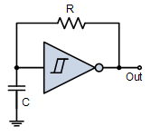
The frequency of the Schmitt Trigger RC oscillator depends on the values of the capacitor and resistor, the hysteresis of the inverter, and the supply voltage. Calculators exist to help predict the frequency, but in practice I’d probably need to tune it experimentally.
I’m fine with some variation in the frequency, as long as it doesn’t vary wildly. A variance of 2x or more could become problematic. Given the tolerance of the capacitor and resistor values, temperature-dependent capacitance changes, process variations between inverters, and possible supply voltage fluctuations, what range of frequency variation is a Schmitt Trigger RC oscillator likely to experience?
Would I be better off paying more for a standard oscillator, even though I don’t need the high accuracy? Or would I be better off using the 4032ZE with its built-in oscillator, and not stressing about the core voltage and pin pitch?
Read 7 comments and join the conversationThe Demon Razor that Wouldn’t Turn Off

What do you do when a battery-powered appliance won’t turn off? And when it’s a sealed unit, so removing the batteries is impossible? And when its body starts to grow disturbingly warm? That’s the situation I found myself in a few days ago.
Riddles in the Dark
I was working at home one night, and gradually became aware of a strange buzzing sound. Initially I thought the sound was outside, but when I went to investigate, I discovered it was coming from the bathroom. My skull shaver, plugged in and recharging, had mysteriously turned itself on and the blades were spinning away. Pressing the on/off button had no effect. Unplugging the charging cable had no effect. The body is a single piece of molded plastic, so there was no non-destructive way of opening it. Nothing could stop the whirrrrrrrrrr of the blades, and the shaver was noticeably warm.
I started to panic that the razor would explode. The internal battery is likely lithium polymer, and from my days with RC cars and aircraft I know that defective or damaged LiPos can fail catastrophically. Like literally go boom and eject flaming molten goo everywhere that burns down your house.

I quickly took the razor outside, and set it on the concrete patio, blades whirring this whole time. A couple of minutes later, I began to fear that it was still too close to the house if it exploded, so I moved it to the street. Thankfully it didn’t explode, and those blades kept whirring for 90 minutes, during which two people stopped to ask what the horrible noise was.
A Tale of Two Chargers
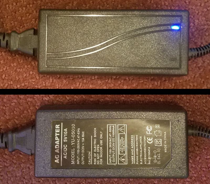
So what caused the skull shaver to go crazy? Bad charging. Besides this manly pink skull shaver, I also own a more conventional Norelco cordless shaver. I’d never noticed it before, but the chargers for the two shavers have the same plug at the end of their cords:

A quick check confirmed that yes, I’d accidentally plugged the skull shaver into the Norelco charger. Is that bad? You might think that the plug shape is standardized, and that all charger plugs with this shape are designed for the same voltage. Let’s check. Here’s the skull shaver charger, which is nicely labeled. 5V output, max 1000 mA:

And here’s the Norelco charger. Instead of a label, its specs are molded into the charger body using impossible to read tiny-sized black-on-black lettering. Yuck.
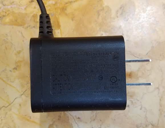
But if it’s tilted at just the right angle to the light, and you get your reading glasses, here’s what emerges:

15 volts! Ouch! I charged a 5 volt device with a 15 volt charger.
I’m suddenly nostalgic for the days when real on/off switches physically disconnected the power. Many of today’s electronic appliances have a soft on/off switch that’s really just an input to some controller circuitry. When soft switches work, they’re great. But when something goes wrong with the control circuit you suddenly have a zombie appliance that can’t be shut off. In the case of this razor, the 15 volts apparently killed the control circuitry before the LiPo battery could be damaged to the point of explosion by over-charging. And the failure mode of the control circuitry was to fail ON.
Have you ever made a similar charging mistake, or exploded a battery through mistreatment? Leave a comment below and tell your story!
Read 8 comments and join the conversationHalloween LED Matrix and PSU Death

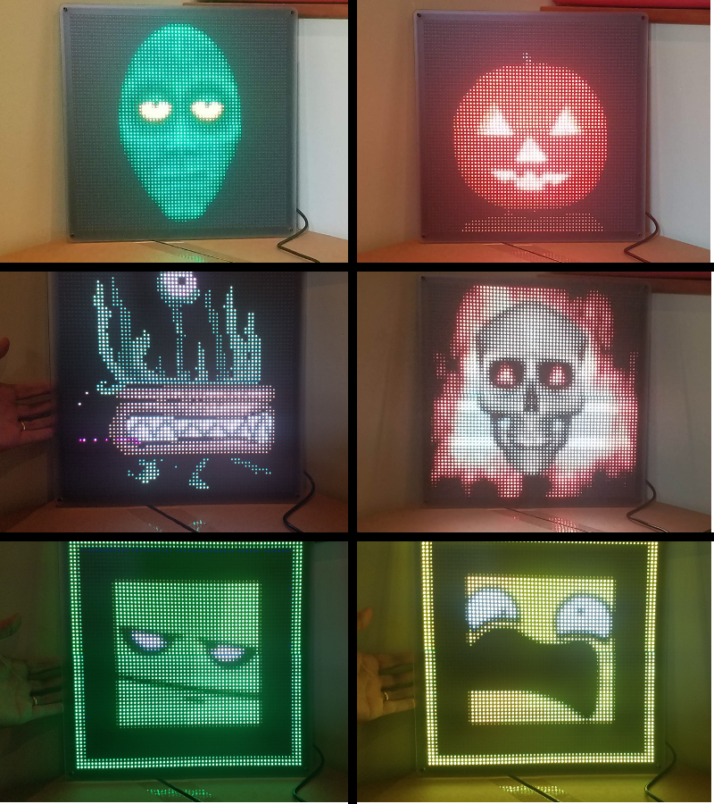
In preparation for Halloween this year, I built a large and colorful LED matrix. After programming it with monster-themed animations, it looked fantastic! Months passed, and when October 31st finally arrived, at dusk I hung the LED display outside by the street. It was to be the perfect lure for neighborhood kids.

But when I checked back an hour later, the LED display was dark and dead. Halloween passed in sad form, with no display of animated monsters. What happened?
LED Matrix ‘Hello World’
This all started last May, when I bought a generic 64 x 32 LED matrix from eBay. These matrix displays are designed to be controlled by an Arduino, Raspberry Pi, or other microcontroller or FPGA. The smallest displays are the simplest: the control unit selects one row of LEDs to illuminate, and then sends a stream of 0’s and 1’s to turn off or on the individual LEDs in that row. In effect, each row of the display is like a large shift register, with each bit corresponding to a separate LED. By cycling rapidly through all the rows, and providing different data for each row, the control unit can create the appearance of the whole LED matrix being lit. For larger displays, two rows can be illuminated at once, using two separate streams of bits, but otherwise the interface is the same.

A blog post from May describes my experiences with that first 64 x 32 LED matrix, using custom software I wrote for an Arduino. It worked well, and the matrix was impressively bright and colorful – the photos can’t do it justice. My custom software was limited to displaying static images, with only 8 colors, because the red, green, and blue LEDs were simply on or off with no in-between state.
Matrix Upgrade
If one matrix is good, two matrixes must be better! I bought a second identical matrix and connected it to the first. These matrixes are designed to be daisy-chained, with the shift-out from one matrix connected to the shift-in of the next. Logically this results in rows that are twice as long as before, creating a 128 x 32 matrix. But physically I arranged the displays to create a 64 x 64 matrix. As a result, the control software became more complicated with mappings between physical and logical lines.
I quickly abandoned my custom Arduino solution, and adopted the excellent rpi-rgb-led-matrix Raspberry Pi library by Henner Zeller. It’s incredibly rich, supporting many different physical to logical mappings, thousands of colors using PWM, video playback, and many other advanced features. Really, if you’re experimenting with one of these LED matrixes, this is the software you want.
For the Raspberry Pi, I selected a Zero W thanks to its built-in WiFi, small size, and rock-bottom price of $10. The OS is a default Raspbian image configured to run in terminal mode. It’s easy to connect to the Pi over WiFi using ssh, and then use rpi-rgb-led-matrix command-line utilities to display images on the LED matrix. It’s a powerful solution, and the only downsides compared to the Arduino are the few seconds required for the Pi to boot up, and the need to perform a clean shutdown instead of just pulling the power plug.
It’s possible to connect the LED matrix directly to the Pi’s GPIO pins, if you don’t mind a squid-like mass of wires. I chose an easier route and bought the Adafruit RGB Matrix Bonnet, which has the same footprint as the Pi Zero and makes the LED matrix connections a breeze. I performed a simple mod to the Adafruit bonnet in order enable hardware PWM to reduce flickering, as described further here. After that it was just plug and play, using the --led-gpio-mapping=adafruit-hat-pwm command-line switch for the rpi-rgb-led-matrix software.
Using the advanced search tools from Google Images, I looked for 64 x 64 animated GIFs with monster-related keywords. In short order I was able to locate several dozen. I was in business!
Building the Frame
To mount the two LED matrix panels together and create an eye-catching display, I built a custom frame. The design was loosely based on this Instructable by Al Linke. It uses several layers of laser-cut acrylic with a pile of carefully-sized spacers and machine screws. The frame took a substantial amount of work, but the end result looks great.
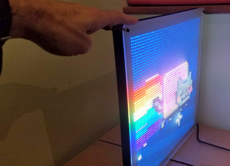
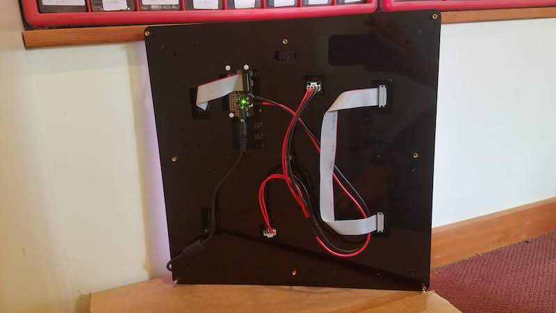
First the LED panels were mounted on a black acrylic piece, with pre-cut holes for mounting screws, wiring, and the Raspberry Pi. The rear of that piece was an ugly and bumpy tangle of cables that wouldn’t hang flat against the wall, so a second black acrylic piece was mounted behind the first to contain the mess. This piece also has integrated mounting holes for a wall hook or picture hanging wire. A third semi-frosted acrylic panel was then mounted on top, to give the LEDs a more diffused look. This is matter of taste, but I found that the LED images looked much nicer with the diffuser panel than without.
Powering the LEDs
In a 64 x 64 matrix, there are 4096 elements. Each element contains separate red, green, and blue LEDs, so the grand total is 12288 LEDs. Assuming that each LED draws 15 mA (a typical number for a single discrete LED), naive math calculates the total current as a whopping 184 amps! Ouch! But this calculation overlooks the fact that only a few rows are actually illuminated at the same time. This particular matrix uses 1:16 multiplexing, so the maximum current is a much more manageable 11.5 amps.
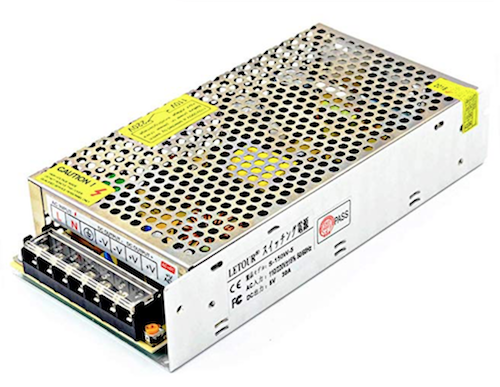
Armed with this information, I purchased the 5V 10A power supply shown here. Why only 10A instead of 11.5A or more? Enclosed “brick” supplies that can provide more than 10 amps are difficult to find, and I expected I’d never need 11.5 amps anyway for real-world images. 11.5A is a worst-case number for a solid white image where every LED is on. My halloween monster images are much darker, typically with many black pixels, so the required current should be much less.
Failure Analysis
When the LED display died on Halloween night, the Raspberry Pi was unresponsive to WiFi connections and the LEDs were dark. The power indicator on the Pi was blinking on and off. Later I noticed that the blue power indicator on the power supply brick was also blinking on and off. Strange.
I brought everything inside and plugged it back in, with the same result. Nothing worked, and the power indicators blinked. At first I thought there must be a short-circuit somewhere in the LED matrix or the Adafruit bonnet, which was repeatedly tripping some protection circuitry in the power supply. But when I disconnected the Pi and the LED matrix, and tried the power supply alone, I observed the same blinking power indicator. The problem was clearly with the power supply itself. Did I exceed its maximum current rating and kill it?
Confused, I left the hardware unplugged for a few days. Later, when I plugged it in again to begin more troubleshooting, I was surprised that it worked! I reconnected the LED display, and everything was great for about an hour. Then it died a second time, with the same blinking power indicator symptom. Uplugging and replugging didn’t help. But if I left it unplugged for a few hours, it would work again the next time it was plugged in.
By this point I was fairly sure I must be over-taxing the power supply and drawing too much current. I guessed that the supply must contain a thermal fuse, and it was overheating and shutting down. Only after a few hours of cooling would it work again, for a short while. 10 amps was simply not enough, it seemed.
To solve my power needs I purchased this 5V 30A “cage” type supply. I was reluctant, because this type of supply isn’t meant for outdoor use, and because it requires wiring to screw terminals instead of using standard power plugs. I’m a reasonably careful person, but I still get nervous playing with bare wires that carry mains voltages. Unfortunately I didn’t see a good alternative.
Before connecting the 30A supply, I decided to do one more test to see how much current the 10A supply was really using. I don’t have an easy way to directly measure the DC current, so I used a Kill-a-Watt meter to measure the power delivered from the wall outlet to the supply. I cycled the LED matrix through its collection of monster images several times, and the highest power measured by the Kill-a-Watt was 19 watts. Hmmm. If I assume the power supply is 80% efficient, then that means it was supplying about 15 watts to the LED matrix. It’s a 5V supply, so that’s a current of only 3 amps maximum – far below the supply’s claimed max of 10 amps. So why did the supply keep shutting off after an hour of use?
While still connected to the Kill-a-Watt, I let the hardware run for a while. This time it took several hours before it shut down, but the end result was the same as before, with dark LEDs and a blinking power indicator. The Kill-a-Watt showed 1 watt. The power supply didn’t feel hot to the touch, but was only slightly warm. This seemed to rule out my “overheating” theory, but didn’t suggest anything else.
Because I’d measured the max current at only about 3 watts, I decided to try a new approach. I pulled out another brick-type power supply from a different project, this one rated at 5 volts and 4 amps max. I connected it to the LED display, and started everything running. It worked just fine, and 18 hours later it’s still running smoothly. Success! At least for this series of Halloween images, it’s all I need.
I’m still curious what caused the first power supply to fail the way it did. Clearly it’s defective or broken somehow, but I’d like to understand more. A 10 amp power supply shouldn’t have any trouble delivering 3 amps continuously. And if it were actually something like a 2 amp power supply, mislabeled as 10 amp, I would expect it to get obviously hot after extended use. But it was never more than slightly warm. Could there be another explanation?
Read 5 comments and join the conversation