Archive for the 'Bit Bucket' Category
Backyard Metal Sand Casting
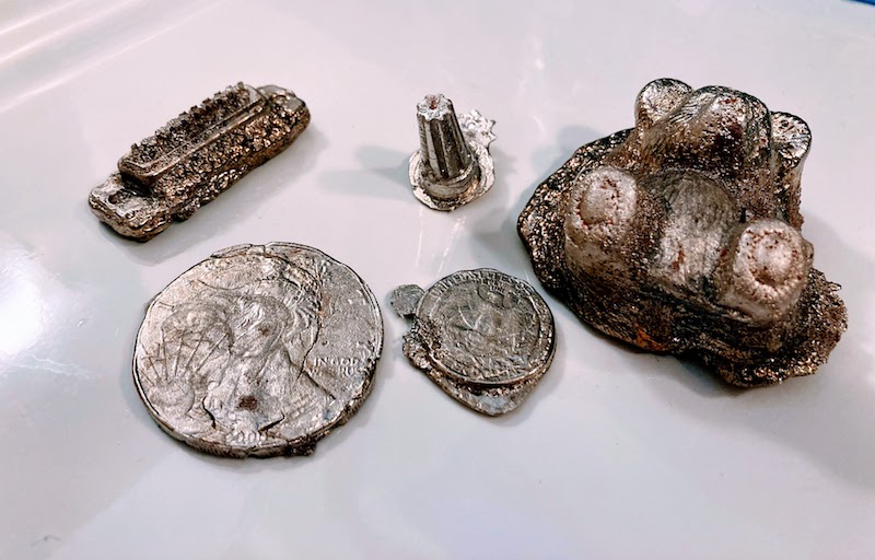
Today’s project: metal casting! I’d been wanting to try this for years, because who doesn’t love playing with molten metal? This was a single-sided open air sand casting process, which is about as simple as it gets. You basically just press an object into some densely-packed sand, remove the object, and pour metal into the resulting sand cavity. Humans have been doing this for thousands of years. Easy peasy, sort of.
This project was a long time coming. I discussed some metal casting ideas last year, and acquired some equipment. Then everything sat on a shelf gathering dust for 13 months.
I used pure bismuth for the casting: atomic number 83 on your periodic table. Bismuth has a pretty low melting point of 521 F / 272 C, easily reached with an electric heater. The objects here are a quarter, a silver dollar, a wire nut, a DB-19 connector, and a teddy bear pencil eraser. A major limitation of this particular process is that the object must have parallel or tapered sides so you can remove it from the sand without disturbing the cavity you just made. That’s why the teddy bear looks like it’s embedded in a rock: I had to dig it out of the sand instead of lifting it out cleanly. This process is also limited to making one-sided reliefs instead of full 3D objects, because the back is just a molten pool of metal directly exposed to the air as it cools.
Sand casting is probably better suited for making tools and gears and big stuff, as opposed to small detailed models like those here, but you can’t beat its simplicity. I made a huge number of mistakes, and the quality is pretty bad, but hey… it worked! Molten metal! Try something, learn something. The images from the coins came through much better than I’d expected, and the teddy bear is pretty neat. I feel like I’ve discovered some secret alchemy with this ancient process.
Sand Casting 101


The traditional sand casting technique uses something called green sand, which is a mix of regular sand, clay, and maybe a bit of other stuff, plus a small amount of water to help it stick together. I used something called Petrobond which is an artificial oil-bonded sand designed specifically for metal casting. When you pack it down tight, it’s very firm – a consistency similar to silly putty or a super dense cheesecake. Either way the grains are small enough to get pretty fine details. Petrobond advertises an average grain size of 0.07 mm.
I began by building a small wooden frame – a four-walled box with no top or bottom. I placed the frame onto a metal lid from a cookie tin to create a temporary floor, then arranged my reference objects inside the frame face-up. I think maybe you’re supposed to dust the objects and the “floor” with a releasing agent, but I didn’t have any, so I skipped this step.
Next, I packed sand into the frame, slowly burying the reference objects. You’re supposed to sift the stuff to break up the chunks and remove any foreign material. My wife vetoed using the kitchen colander or sifter, and my DIY sifter built from window screen failed miserably, so my Petrobond didn’t get sifted properly. I packed it in as tightly as possible with my hands, then rammed it down hard with the base of a heavy flashlight. The top surface of the sand was scraped level with the frame, using a metal ruler. I then carefully flipped over the frame and removed the cookie tin lid. Because the sand was packed very tightly, it did not fall out. I placed the inverted frame back onto the cookie tin lid, with the reference objects now exposed.
The objects were perfectly flush with the surface of the dense-packed sand. How do you remove them without disturbing the sand? There must be some secret method that I’ve yet to learn. I damaged the mold substantially in the process of removing the objects, and also spilled loose sand into mold cavities. There was a lot of swearing involved.
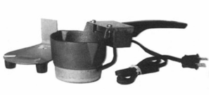
The final step was to melt the bismuth and pour it into the mold cavities. This was somewhat anti-climactic. I used an electric ladle to melt a one pound chunk of pure bismuth purchased from rotometals.com. It took a few minutes to melt, and smelled like a tire fire. I’m not sure if the smell came from the bismuth or from the ladle, but it was terrible and I feared my neighbors would complain. Once melted, I poured the bismuth into the molds like soup into a bowl. I let everything cool down for about an hour before digging the castings out of the sand.

Room for Improvement
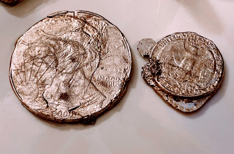
I was happy to get “read the lettering on a quarter” level of detail in some areas, but the final casting results were mixed. I would have gotten better results and finer detail if I’d been more careful with removing the original coins from the mold, and poured the metal faster. You can see where the silver dollar partially cracked due to uneven cooling. This happened when I poured some bismuth into that mold, but not enough to fill it fully, and then waited a few seconds before pouring in the rest. I was trying to avoid overflowing.
Bismuth probably wasn’t the best material for this project. It has a low melting point and is comparatively non-toxic, but it’s brittle. Next time I may try pewter or another low temperature alloy that’s specifically intended for metal casting.
When you heat the bismuth, or most any other metal except gold, the surface of the molten metal reacts with oxygen in the air to create an oxide layer. You’re supposed to skim this off before pouring the metal into your molds. I forgot to keep skimming tools at the ready, so my oxide layer dregs went into the mold along with everything else.
The biggest improvement would be graduating to two-sided casting, using two sand frames that lock together. You can buy ready-made frame sets inexpensively. But even after reading several tutorials about the process, I still don’t really understand how the two-sided mold making works. I’m sure it’s very simple, but something about the geometry of it still escapes me.
Read 4 comments and join the conversationApple II Video Card Thoughts
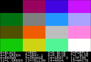
Recently I’ve been toying with the idea of building an Apple II video card. Like many of you, I’ve grown tired of searching for the dwindling supply of monitors with a native composite video input, and frustrated with available solutions for composite-to-VGA and composite-to-HDMI conversion. This card would fit in an expansion slot of an Apple II, II+, IIe, or IIgs, and provide a high quality VGA output image suitable for use with a modern computer monitor. I welcome your thoughts on this idea.
Why Do This?
Another Apple II video solution? Aren’t there enough options already? It’s true there have been many different Apple II VGA solutions over the years, and a smaller number of HDMI solutions. Unfortunately almost all of them have been retired, or have very limited availability. I’m also interested in this project as a personal technology challenge. It could combine some of my past experience with Yellowstone (Apple II peripheral cards) and Plus Too and BMOW1 (VGA video generation).
How Would It Work?
I see three possible paths for a high-quality Apple II VGA video solution. One is to convert the signals from the computer’s external monitor port. But monitor ports are only present on the Apple IIc and IIgs, and so that wouldn’t meet my goals. The second approach is to tap into a few key video-related signals directly from the motherboard, before they’re combined to make the composite video output. This is a viable approach, and others have been successful using this method. The downside is that it requires a snarl of jumper wires and clips attached to various points on the motherboard, and the details vary from one motherboard revision to the next.
I’m considering a third approach: design a peripheral card that listens to bus traffic, watches for any writes to video memory, and shadows the video memory data internally. Then the card will generate a VGA video output using the shadowed video memory as its framebuffer. It’s simple in concept, but maybe not so simple in the details. The first two approaches require only a comparatively dumb device to do scan conversion and color conversion. In contrast, the bus snooping approach will require the video card to be a smart device that’s able to emulate all the Apple II’s video generation circuitry – its weird memory layouts and mixed video modes and character ROM and page flipping and everything else. But it promises a simple and easy solution when it comes time to use the card. Just plug it in and go.
To be specific, for basic support of text and LORES/HIRES graphics, the card will need to shadow writes to these memory addresses:
$0400-$07FF TEXT/LORES page 1
$0800-$0BFF TEXT/LORES page 2
$2000-$3FFF HIRES page 1
$4000-$5FFF HIRES page 2
and these soft switches:
$C050/$C051 graphics / text
$C052/$C053 mix / no mix
$C054/$C055 page 1 / page 2
$C056/$C057 lores / hires
Can It Work?
For basic 40 column text mode, I hesitate to say this will be easy, but I don’t anticipate it being difficult. LORES and HIRES graphics may be more challenging, because the memory layouts are increasingly strange, and because determining what color to draw will depend on careful study of NTSC color artifact behavior. But I’m relatively optimistic I could get this all working well enough for it to be useful.
After finishing the basics, there will remain several more difficult challenges. First among these is sync. If the vertical blank of the VGA image isn’t synchronized with the vertical blank of the Apple II’s composite video, then tearing or flickering may be visible in the image. Carefully-timed program loops that attempt to change video memory only during blank periods won’t work as intended. Fortunately motherboard revisions 1 and later provide the SYNC signal to peripheral cards in slot 7, which can be used to synchronize the VGA and composite video outputs. For installation in a different slot or on a revision 0 motherboard, a wire can be connected to the motherboard for the SYNC signal, or the card can run unsynchronized.
What about European PAL models of the Apple II? I think Eurapple machines should work OK, since the card’s function is based on bus snooping rather than the actual video data. The VGA output will be the same, since fortunately there are no NTSC/PAL distinctions to worry about for VGA video. I’m less sure about Eurocolor machines. I believe these already have slot 7 occupied with an Apple video card – can anyone confirm? If so, my video card will have to go in a different slot, where the SYNC signal won’t be available. That’s probably no great loss, since software designed to sync with a 50 Hz composite PAL display can’t be synchronized with 60 Hz VGA anyway.
Can double-hires graphics and 80 column text be handled too? I think so, but I haven’t looked at these modes in much detail yet. From what I’ve seen, they both involve bank switching RAM between the main and AUX banks. Supporting these modes would mean shadowing some additional areas of memory, and a few more soft switches that control bank switching, as well as more software complexity. But they should be doable.
Non-standard character ROMs are another question. The video card will need to duplicate the contents of the character ROM in order to generate text. The most obvious solution is to simply assume the character ROM is a standard one, and include a copy of the standard character ROM on the card. But in some models of Apple II, it’s possible to replace the normal character ROM with a ROM containing an international character set in place of the inverse characters. These seem to have been common for Apple II computers sold in several countries. My card won’t know about the custom character ROM, and won’t render those characters correctly. I don’t see any easy answer for this issue. Possibly the card could use DMA to read the character ROM, but that would be a major increase in complexity.
Finally there’s the question of the Apple IIgs. Will the card even work in a IIgs? Maybe not, if writes to video memory on the IIgs are handled specially, and the address and data never appear on the peripheral card bus. That will be easy enough to test. Another question to consider is super hires graphics on the IIgs. I don’t know anything about how this works. I can’t think of any fundamental reason it couldn’t be handled in the same way as the other graphics modes, but it might be very complex.
Hardware Choices
What kind of hardware would be appropriate for a video card like this? It needs at least 18K of RAM to shadow the memory regions for text, LORES, and HIRES graphics. If 80 column text and double-HIRES are also supported, then the RAM requirement grows to something like 54K. The hardware must also be fast enough to snoop 6502 bus traffic and to shadow memory writes that may appear as often as every 2 microseconds. And it must also be capable of generating a VGA output signal with consistent timing and a pixel clock about 25 MHz.
What about something like a Raspberry Pi? Yeah… it might work, but it’s not at all the kind of solution I would choose. Those who’ve read my blog for a while know that while I’ve used the Raspberry Pi in a few projects, it’s not my favorite tool. I strongly prefer solutions that keep as close to the hardware as possible, where I can control every bit and every microsecond. That’s where the fun is.
Could it be done with a fast 32 bit microcontroller, something like an STM32? 54K of RAM would be no problem, and a 100 MHz microcontroller could probably handle an interrupt every 2 microseconds just fine. That would be enough to snoop the 6502 bus and shadow the writes to RAM. I’m less confident that a microcontroller could directly generate the required VGA output signal. If the caches could be disabled, it might be possible to write carefully-timed software loops to output the VGA signal. But the interrupts for RAM shadowing would probably screw that up, and make a hash out of the VGA signal timing.
A small FPGA is probably the solution here. 54K is rather a lot of built-in RAM for an FPGA, so the FPGA would need to be paired with an external RAM of some type – most likely SRAM or a serial RAM. Or the FPGA could be paired with a microcontroller, providing both RAM and some extra processing horsepower.
Read 51 comments and join the conversationHow Many Bits in a Track? Revisiting Basic Assumptions

Yesterday’s post contained lots of details about Apple II copy-protection and the minutiae of 5.25 inch floppy disk data recording. It mentions that bits are recorded on the disk at a rate of 4 µs per bit. This is well-known, and 4 µs/bit appears all over the web in every discussion of Apple II disks. This number underpins everything the Floppy Emu does involving disk emulation, and has been part of its design since the beginning. But as I learned today, it’s wrong.
Sure, the rate is close to 4 µs per bit, close enough that disk emulation still works fine. But it’s not exactly right. The exact number is 4 clock cycles of the Apple II’s 6502 CPU per bit. With a CPU speed of 1.023 MHz, that works out to 3.91 µs per bit. That’s only a two percent difference compared with 4 µs, but it explains some of the behavior I was seeing while examining copy-protected Apple II games.
With the disk spinning at 300 RPM, it’s making one rotation every 200 milliseconds. 4 µs per bit would result in 50000 bits per track, assuming a disk is written using normal hardware with a correctly calibrated disk drive. 50000 is also the number of bits per track given in the well-known book Beneath Apple DOS. But it’s wrong. At 3.91 µs per bit, standard hardware will write 51150 bits per track.
Not content to trust any references at this point, I measured the number directly using a logic analyzer and a real Apple IIe and Apple IIgs. When writing to the disk, both systems used a rate of about 3.92 µs per bit. Here’s a screen capture from a test run with the Apple IIe, showing the time for 10 consecutive bits at 39.252 µs. There was some jitter of about 50 nanoseconds in the measurements, and measuring longer spans of bits revealed an average bit rate of about 3.9205 µs. That’s a tiny difference versus 3.91 µs. Can I say it’s close enough, and let it go? Of course not.
Even the advertised CPU speed of 1.023 MHz is inaccurate, so what is it really? The Apple II’s CPU clock is actually precisely 4/14ths the speed of the NTSC standard color-burst frequency of 3.579545 MHz. (This number can be derived as 30 frames/sec times 525 lines/frame times 455/2 cycles/line divided by a correction factor of 1.001.) 3.579545 MHz times 4 divided by 14 is 1.02272714 MHz. Rounded to three decimal places that gives the advertised CPU speed of 1.023 MHz. But using the exact CPU frequency, four clock cycles should be 3.91111 µs. There’s still a discrepancy of slightly less than 0.01 µs compared with my measurements, hmmm.
But wait! In the comments to the answer to this Stack Exchange question, it’s mentioned that every 65th clock cycle of the Apple II is 1/7th longer than the others, because of weird reasons. That means the effective CPU speed is slower than I calculated by a factor of 1/(65*7). In light of this, I calculate a new average CPU speed of precisely 1.020479520466562 MHz, and a time for four clock cycles of about 3.9197 µs. That’s a difference of only 0.0008 µs from my measurement – less than one nanosecond. Ah ha! So everything makes sense, and my measurements were correct.
The difference between 4 µs per bit and 3.92 may seem like a minor detail, but for a floppy disk emulator developer, it’s like suddenly discovering that the value of pi is not 3.14159 but 3.2. My mind is blown.
Read 1 comment and join the conversationWindows 10 External Video Crashes Part 6 – Conclusion

For most of 2019 I was going crazy trying to solve unexplained problems with Windows 10 external video on my HP EliteBook x360 1030 G2 laptop. I bought the computer last May, with the idea to use it primarily as a desktop replacement. But when I connected an ASUS PB258Q 2560 x 1440 external monitor, I was plagued by mysterious intermittent crashes that slowly drove me insane. For the previous chapters of this story, see part 1, part 2, part 3, part 4, and part 5.
The computer worked OK during normal use, but problems appeared every couple of days, after a few hours of idle time or overnight. I experienced random crashes in the Intel integrated graphics driver igdkmd64.sys, though these stopped after upgrading the driver. The computer periodically locked up with a blank screen and fans running 100%. The Start menu sometimes wouldn’t open. Sometimes the Windows toolbar disappeared. Sometimes I’d return to the computer to find the Chrome window resized to a tiny size.
The crowning moment was the day I woke from the computer from sleep, and was greeted with the truly bizarre video scaling shown in the photo above. The whole image was also inset on the monitor, with giant black borders all around.
These might sound like a random collection of symptoms, or like a software driver problem, or maybe a typical problem with bad RAM or other hardware. But after pretty exhaustive testing and analysis (did I mention this is part 6 of this series), I became convinced the problem was somehow related to the external video. The problems only occurred when connected to external video, and when the external video resolution was 2560 x 1440.
I tried different cables. I tried both HDMI and DisplayPort. I tried RAM tests, driver updates, and firmware updates. I tried what seemed like a million different work-arounds. And I tried just living with it, but it was maddening.
Out With the Old
After seven months of this troubleshooting odyssey, in late December I finally gave up and replaced the whole computer. I purchased a Dell desktop, which is probably what I should have done in the first place. My original idea of using the laptop mostly as a desktop seemed attractive, but in actual practice I never made use of the laptop’s mobility. It functioned 100% as a desktop, except it was more expensive than a desktop, with a slower CPU than a comparable desktop, and with more problems than a desktop. For example, the external keyboard and monitor didn’t work reliably in the BIOS menu – I had to open the laptop and use the built-in keyboard and display. Waking the computer from sleep with the external keyboard was also iffy. I eventually concluded that a “desktop replacement” laptop isn’t really as good as a real desktop computer.
I’m happy to report that the new Dell desktop has been working smoothly with the ASUS PB258Q 2560 x 1440 monitor for five months. But what’s more surprising is that the EliteBook laptop has also been working smoothly. My wife inherited the EliteBook, and she’s been using it daily without any problems. She often uses it with an external monitor too, although it’s a different one than the PB258Q monitor I was using. No troubles at all – everything is great.
So in the end, everything’s working, but the problem wasn’t truly solved. Can I make any educated guesses what went wrong?
All the evidence points to some kind of incompatibility between the PB258Q’s 2560 x 1440 resolution and the EliteBook x360 1030 G2. Other monitors didn’t exhibit the problem, and other video resolutions on the same monitor didn’t exhibit the problem either. I believe the external video was periodically disconnecting or entering a bad state, causing the computer to become confused about what monitors were connected and what their resolutions were. This caused errors for the Start menu, toolbar, and applications, and sometimes caused the computer to freeze or crash. Was it a hardware problem with the EliteBook, a Windows driver problem, or maybe even a hardware problem with the ASUS monitor? With a large enough budget for more hardware testing, I might have eventually found the answer. For now I’m just happy the problem is gone.
Be the first to comment!Building a 12V DC MagSafe Charger
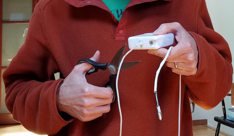
Now that I have a solar-powered 12V battery, how can I charge my laptop from it? An inverter would seem absurdly inefficient, converting from 12V DC to 110V AC just so I can connect my Apple charger and convert back to DC. It would work, but surely there’s some way to skip the cumbersome inverter and charge a MacBook Pro directly from DC?
Newer Macs feature USB Type C power delivery, a common standard with readily available 12V DC chargers designed for automotive use. But my mid-2014 MBP uses Apple’s proprietary MagSafe 2 charging connector. In their infinite wisdom, Apple has never built a 12V DC automotive MagSafe 2 charger – only AC wall chargers. There are some questionable-looking 3rd-party solutions available, but I’d rather build my own.
Step 1: Cut the cord off a MagSafe 2 AC wall charger. Yes that’s right. Being a proprietary connector, there’s no other source for the MagSafe 2. Fortunately I already had an old charger with a cracked and frayed cable that I could use as a donor. Snip!
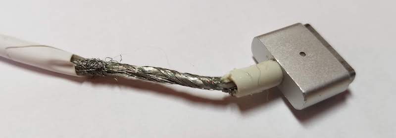
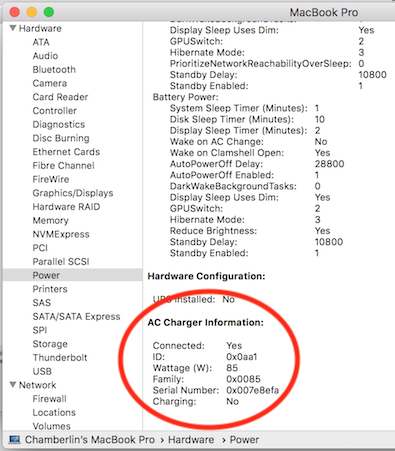
The choice of AC wall charger matters more than you might expect. Inside the MagSafe 2 connector is a tiny chip that identifies the charger type and its maximum output power. The Mac’s internal charging circuitry won’t exceed this charging power, no matter what the capabilities of the power supply at the other end of the cable. Pretty sneaky, Apple! Official MagSafe 2 chargers come in three varieties of 45W, 65W, and 85W. My donor MagSafe 2 has the 85W id chip inside, so I can charge at the fastest possible rate.
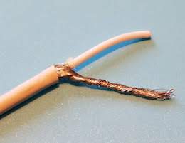
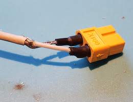
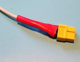
After cutting the charger cable, inside I found another insulated wire which I assumed to be the positive supply, surrounded by a shroud of fine bare wires which I assumed to be the ground connection. I’m not sure why Apple designed the cable this way, instead of with two separate insulated wires for power and ground. The braid of fine bare wires was awkward to work with, but I eventually managed to separate it and twist it into something like a normal wire. I soldered the power and ground wires to an XT60 connector and covered them with electrical tape and heat shrink. I also repaired the cracked and frayed cable sections.
Step 2: Get a DC-to-DC boost regulator. The input should be 12V, with a few volts of margin above and below. But what about the output? What’s the voltage of a MagSafe 2 charger? My donor charger says 4.25A 20V, but I couldn’t find any 12V-to-20V fixed voltage boost regulators. Happily I think anything roughly in the 15-20V range will work. For comparison, I have a 45W Apple charger that outputs 14.85V and a 3rd-party MagSafe 2 charger that outputs 16.5V. I chose this 12V-to-19V boost regulator with a maximum output power of 114W. At 85W, I’ll be pushing it to about 75% of maximum.
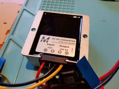
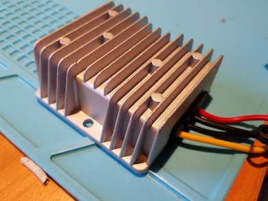
Step 3: The moment of truth. Would my expensive computer burst into flames when I connected this jury-rigged DC MagSafe charger? I held my breath, plugged in the cable, and… success! Of course it worked. The orange/green indicator LED on the MagSafe 2 connector worked too.
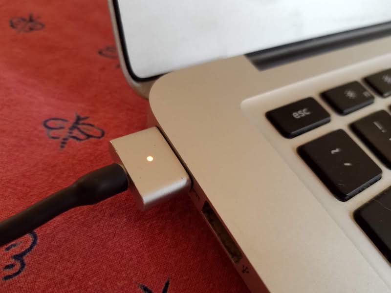
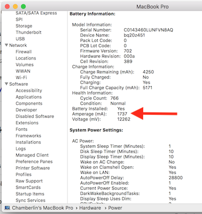
Opening the Mac’s System Information utility and viewing the Power tab, I could see that my charger was correctly recognized and working. The “Amperage” status also showed the battery was charging at a rate of 1737 mA (positive numbers here indicate charging, and negative numbers discharging). This seemed low – with the battery at 12.2V, that implied it was charging at roughly 21W instead of 85W. But when I connected an AC wall charger in place of my DC charger, the charging rate was almost identical. Because my battery was almost 100% charged, I think the charging rate was intentionally reduced. I’ll check again later when my battery is closer to 0%.
Goodbye, inverter. With just a few hours of work, I had a functioning 12V DC MagSafe 2 charger. Time to sit back, enjoy a beer, and celebrate victory.
Checking the Numbers
I like numbers. Do you like numbers? Here are some numbers.
This charging method is about 95% efficient, according to the claimed efficiency rating of the boost regulator. I can also leave the regulator permanently connected, since its no-load current is less than 20 mA. In comparison, charging with an inverter and an AC wall charger is about 77% efficient (85% for the inverter times 90% for the wall charger). And an inverter probably can’t be left permanently connected, since it has a constant draw of several watts even when no appliances are plugged in.
My “12V battery” is actually a Suaoki portable power station with a 150 Wh battery capacity. How many times can I recharge my MacBook Pro from this? Checking the Mac’s System Information data, I infer it has a 3S lithium battery with an 11.1V nominal voltage. System Information says the battery’s fully-charged capacity is 5182 mAh (which means my battery is old and tired), so that’s 57.5 Wh. A bit of web searching reveals that a fresh battery should have a capacity of 71.8 Wh. That means I should be able to recharge my MBP from 0% up to 100% twice, before exhausting the Suaoki’s 150 Wh battery.
Is the charging current over-taxing the Suaoki? How much current am I actually drawing from it? 85W of output power with 95% efficiency implies about 89.5W of input power to the boost regulator. At 12V that would be roughly 7.5A drawn from the Suaoki battery. But the Suaoki’s lithium battery falls to about 9V before it’s dead, and at 9V it would take 10A to reach the same number of watts. The Suaoki’s 12V outputs are rated “12V/10A, Max 15A in total”, so in the worst case I’d be running right up to the maximum.
What happens if I charge my MacBook and charge a couple of phones from the Suaoki’s USB ports at the same time? Would this be too much? I wouldn’t be exceeding the maximum rating of the USB ports, and (probably) wouldn’t be exceeding the maximum rating of the 12V ports, but the combination might be too much. At 85W for the MacBook, and maybe 10-20W each for two phones, the worst-case total could be as much as 125W. The Suaoki manual says “the rated input power of your devices should be no more than 100W”, but I think this refers to the AC inverter, not the system as a whole. Powering 125 watts from a 150 Wh battery is a discharge rate under 1C, which seems quite reasonable for a lithium battery. It’s probably OK. Now, back to charging!
Read 32 comments and join the conversationResidential Solar Power and the Duck Curve
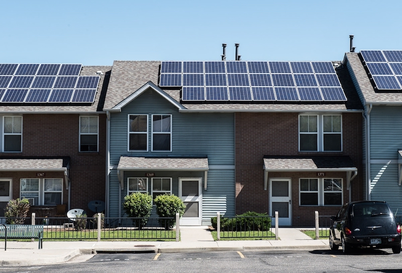
Sometimes you can have too much of a good thing. Take a look at the growth of residential roof-top solar power in California. For individual customers who are blessed with sunny weather, installing solar panels can be a smart financial decision and a great way to escape the region’s high electricity prices. But for the utility companies and for the region as a whole, the results may not be what you’d expect. On sunny California afternoons, the state’s wholesale electric prices can actually turn negative. There’s a glut of electric generation, supply exceeds demand, but all that electricity has to go somewhere. So factories are literally paid to use electricity.
Negative Electricity Prices
What is going on here? It’s important to understand that all electric usage must be matched with electric generation occurring at the same moment. Aside from a few small-scale systems, there’s no energy storage capability on the grid. If customers are using 5 gigawatts, then there needs to be 5 gigawatts of total generation from power plants at that same time. If there’s not enough generation, you get brownouts. And if there’s too much generation, you either get over-voltage or over-frequency, damaged equipment, fires, and other badness.
Maintaining this balance is difficult. Electric demand is constantly changing, but it’s not so easy to switch a gas-fired power plant on and off. There’s some ability to adjust output, but it’s not perfect. For most residential solar installations, the utility company is obligated to buy any excess electric generation, whether they need it or not. There’s no way for the utility company to tell you “thanks but we already have enough power right now, please disconnect your solar panels”. So what happens when there’s too much electricity? You pay somebody to take it.
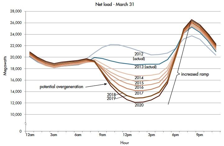
The challenge is illustrated by something called the duck curve, so-named because the graph supposedly looks like a duck. This curve shows the hour-by-hour net electricity demand for California, after excluding solar power. As the day starts, net demand is about 19 GW. Then around 8:00 AM, the sun rises high enough above horizon obstructions and solar power begins to flood the grid. Net demand from gas and coal power plants drops hard. Then around 6:00 PM the trend reverses. As the sun is setting, solar power generation declines to zero while everyone switches on lights and air conditioning. Net demand skyrockets, creating a huge demand wall peaking about 26 GW at 8:00 PM. It’s enough to make any grid operator swoon.
Every year, this problem gets worse as more and more residential customers install solar panels. This trouble is likely to grow even faster now due to California’s new first-of-its-kind solar mandate. As of January 1st 2020, the state requires that all newly-constructed homes have a solar photovoltaic system. Expect the duck curve to quack even more than before.
It’s not hard to understand why grid operators view residential solar as a mixed blessing. During the day it provides cheap clean electricity, and that’s a good thing. Gas and coal plants can be idled, saving fuel and reducing emissions. But solar power can’t eliminate those gas and coal plants entirely – they’re still critically important for evenings and night. So during the day many of those plants are just sitting there doing nothing. The power plants still need to be built, and staffed, and maintained, even if they’re only in use half the time.
Grid-Scale Energy Storage
Given the daytime production of solar power, there’s no amount of solar that could ever replace 100% of the state’s energy needs. By itself, it will never enable us to get rid of all those gas and coal power plants. That’s a big problem – a huge problem if you care about the long term and the environment. If you’re a young engineer casting about for a field in which to make your career, I believe you could do very well dedicating your career to solving this challenge.
The answer of course is energy storage. What’s needed is a way to take the dozens of GWh of solar power generated between 8:00 AM and 6:00 PM, and spread it out evenly across a 24 hour period. But how?
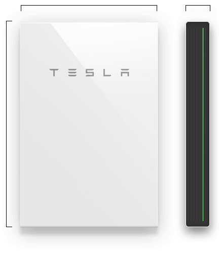
You might be thinking of solutions like the Tesla Powerwall, or similar home-based battery storage systems. The Powerwall 2 is a very cool device that can store 13.5 kWh. You can use it to store excess power generated by your solar panels during the day, and drain it at night to run your lights and appliances, helping to smooth out the duck curve.
But the Powerwall is too small and too expensive to really make economic sense. 13.5 kWh is not enough to get a typical home through the night, and the hardware costs about $13000 installed with a 10-year lifetime. You’d need to achieve massive cost savings for the Powerwall to pay for itself during those 10 years. It’s good for the utilities, and if every residential solar customer had a Powerwall, it would go a long way towards smoothing the duck curve and eliminating many of those gas and coal power plants. But it’s probably not a good value for you, the individual residential customer.
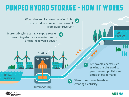
Image from arena.gov.au
Looking at the whole system, what’s really needed is grid-scale energy storage. Instead of individual customers storing a few tens of kWh with batteries, we need industrial-scale systems storing many MWh or GWh by pumping millions of gallons of water uphill or with other storage techniques. These are big engineering projects, and some effort has already been made in this direction, but it’s still early days. Aside from massive battery arrays and pumping water uphill, other options include heating water and storing compressed air underground. Nothing works very well yet, but watch this space. The world needs this.
TLDR: It matters not only how much clean energy can be generated, but when it’s generated. The variable output of solar power is a big problem that prevents eliminating more gas and coal power plants. A large scale energy storage solution that’s cheap and efficient would be a tremendous win.
Read 7 comments and join the conversation
