

Archive for the 'Bit Bucket' Category
Raspberry Pi GPIO Programming in C
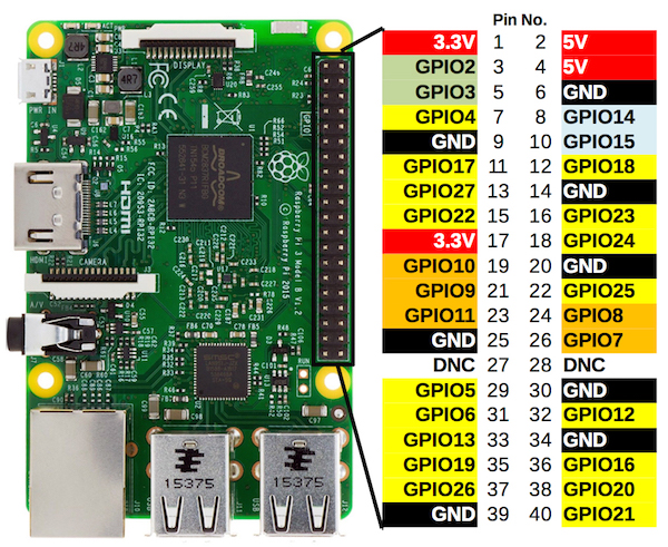
The Raspberry Pi’s 40-pin GPIO connector often gets overlooked. Typical Pi projects use the hardware as a very small desktop PC (RetroPie, Pi-hole, media center, print server, etc), and don’t make any use of general-purpose IO pins. That’s too bad, because with a little bit of work, the Raspberry Pi can make a powerful physical computing device for many applications.
Raspberry Pi vs Arduino (and other microcontrollers)
Why would you want to use a Raspberry Pi instead of an Arduino or other microcontroller (STM32, ATSAM, PIC, Propeller)? There are loads of “Raspberry Pi vs Arduino” articles on the web, and in my view almost all of them miss the mark. The Pi is not a better, more powerful Arduino. It’s a completely different type of device, better at some tasks, but markedly worse at others.
The Pi is vastly more powerful than something like an Arduino Uno. The latest Pi 3 Model B+ has an 88x faster CPU clock and 500,000x more RAM than the Uno. It also runs a full-fledged Linux operating system, so it’s much easier to create projects involving high-level functions like networking or video processing. And you can connect a standard keyboard, mouse, and monitor, and use it as a normal computer.
But the Pi operating system is also a huge weakness in many applications. There’s no “instant on”, because it takes nearly a minute for the device to boot up. There’s no appliance-like shutoff either – the Pi must be cleanly shutdown before power is turned off, or else the operating system files may get corrupted. And real-time bit twiddling of GPIO is mostly impossible, because the kernel may swap out your process at any moment, making precise timing unpredictable.
In theory it’s possible to do bare-metal programming on the Raspberry Pi, eliminating Linux and its related drawbacks for real-time applications. Unfortunately this doesn’t seem to be a common practice, and there’s not much information available about how to do it. So the Pi is probably best for those applications where you need some major CPU horsepower and some kind of GPIO connection to other sensors or equipment, but don’t need precise real-time behavior or microsecond-level accuracy.
GPIO and Python?
If you start Googling for “Raspberry Pi GPIO programming”, you’ll quickly discover that most of the examples use the Python language. In fact, this seems to be the most popular way by far to use GPIO on the Pi.
I have nothing against Python, but I’m a C programmer through and through, and the idea of using a high-level language for low-level digital interfaces is unappealing. By one measure, Python is over 300x slower at Raspberry Pi GPIO manipulation than plain C. I’m sure there are applications where it’s OK to throw away 99.7% of potential performance, but I’ll be sticking with C, thank you very much.
I spent a little time researching four different methods of Raspberry Pi GPIO manipulation in C. This involved reading documentation and data sheets, and examining the source code of various libraries. I haven’t yet tried writing any code using these methods, so take my impressions accordingly.
If any of the authors of these C libraries happen to read this – thank you for your work, and please don’t be offended by any criticisms I may make. I understand that creating an IO library necessarily involves many tradeoffs between simplicity, speed, flexibility, and ease of use, and not everyone will agree on the best path.
Direct Register Control – No Library
The GPIO pins on the Raspberry Pi can be directly accessed from C code, similarly to how it’s done on the ATMEGA or other microcontrollers. A few different memory-mapped control registers are used to configure the pins, and to read input and set output values. The only big difference is that the code must first call mmap() on /dev/mem or /dev/gpiomem, to ask the kernel to map the appropriate region of physical memory into the process’s virtual address space. If that means nothing to you, don’t worry about it. Just copy a couple of dozen lines of code into your program’s startup routine to do the mmap, and the rest is fairly easy.
Here’s an example of reading the current value of GPIO 7:
if (gpio_lev & (1<<7))
  // pin is high
else
  // pin is low
Just test a bit at a particular memory address - that's it. This looks more-or-less exactly like reading GPIO values on any other microcontroller. gpio_lev is a memory-mapped register whose address was previously determined using the mmap() call during program initialization. See section 6 of the BCM2835 Peripherals Datasheet for details about the GPIO control registers.
Setting the output value of GPIO 7 is similarly easy:
gpio_set |= (1<<7); // sets pin high

gpio_clr |= (1<<7); // sets pin low
Using other control registers, it's possible to enable pull-up and pull-down resistors, turn on special pin functions like SPI, and change the output drive strength.
Watch out for out-of-order memory accesses! The datasheet warns that the system doesn't always return data in order. This requires special precautions and the use of memory barrier instructions. For example:
a_status = *pointer_to_peripheral_a;
b_status = *pointer_to_peripheral_b;
Without precautions, the values ending up in the variables a_status and b_status can be swapped. If I've understood the datasheet correctly, a similar risk exists for GPIO writes. Although data always arrives in order at a single destination, two different updates to two different peripherals may not be performed in the same order as the code. These out-of-order concerns were enough to discourage me from trying direct register IO with my programs.
Wiring Pi
WiringPi wraps the Raspberry Pi GPIO registers with an API that will look very familiar to Arduino users: digitalRead(pin), digitalWrite(pin, value). It's a C library, but third parties have added wrappers for Python and other high-level languages. From a casual search of the web, it looks like the most popular way to do Raspberry Pi GPIO programming in C.
WiringPi appears to be designed with flexibility in mind, at the expense of raw performance. Here's the implementation of digitalRead():
int digitalRead (int pin)
{
  char c ;
  struct wiringPiNodeStruct *node = wiringPiNodes ;

  if ((pin & PI_GPIO_MASK) == 0)		// On-Board Pin
  {
    /**/ if (wiringPiMode == WPI_MODE_GPIO_SYS)	// Sys mode
    {
      if (sysFds [pin] == -1)
	return LOW ;

      lseek  (sysFds [pin], 0L, SEEK_SET) ;
      read   (sysFds [pin], &c, 1) ;
      return (c == '0') ? LOW : HIGH ;
    }
    else if (wiringPiMode == WPI_MODE_PINS)
      pin = pinToGpio [pin] ;
    else if (wiringPiMode == WPI_MODE_PHYS)
      pin = physToGpio [pin] ;
    else if (wiringPiMode != WPI_MODE_GPIO)
      return LOW ;

    if ((*(gpio + gpioToGPLEV [pin]) & (1 << (pin & 31))) != 0)
      return HIGH ;
    else
      return LOW ;
  }
  else
  {
    if ((node = wiringPiFindNode (pin)) == NULL)
      return LOW ;
    return node->digitalRead (node, pin) ;
  }
}
That's a lot of code to accomplish what could be done by testing a bit at an address. To be fair, this code does a lot more, such as an option to access GPIO using sysfs (doesn't require root?) instead of memory-mapped registers, and pin number remapping. It also adds a concept of on-board and off-board pins, so that pins connected to external GPIO expanders can be controlled identically to pins on the Raspberry Pi board itself.
From a brief glance through the source code, I couldn't find any use of memory barriers. I'm not sure if the author determined that they're not necessary somehow, or if out-of-order read/writes are a risk.
WiringPi also includes a command line program called gpio that can be used from scripts (or interactively). It won't be high-performance, but it looks like a great tool for testing, or for when you just need to switch on an LED or something else simple.
pigpio

pigpio is another GPIO library, and appears more geared towards simplicity and speed. And yes, it was quite a while before I recognized the name was Pi GPIO, and not Pig Pio. 🙂
Here's pigpio's implementation of gpioRead():
#define BANK (gpio>>5)
#define BIT  (1<<(gpio&0x1F))

int gpioRead(unsigned gpio)
{
   DBG(DBG_USER, "gpio=%d", gpio);

   CHECK_INITED;

   if (gpio > PI_MAX_GPIO)
      SOFT_ERROR(PI_BAD_GPIO, "bad gpio (%d)", gpio);

   if ((*(gpioReg + GPLEV0 + BANK) & BIT) != 0) return PI_ON;
   else                                         return PI_OFF;
}
Here there's no pin number remapping or other options. The function does some error checking to ensure the library is initialized and the pin number is valid, but otherwise it's just a direct test of the underlying register.
As with WiringPi, I did not see any use of memory barriers in the source code of pigpio.
bcm2835
bcm2835 is a third option for C programmers looking for a Raspberry Pi GPIO library. It appears to have the most thorough and well-written documentation, but also seems to be the least commonly used library of the three that I examined. This may be a result of its name, which is the name of the SoC used on the Raspberry Pi. It's somewhat difficult to find web discussion about this library, as opposed to the chip with the same name.
Like pigpio, bcm2835 appears more focused on providing a thin and fast interface to the Pi GPIO, without any extra options. Here's the implementation of bcm2835_gpio_lev(), the oddly-named read function:
uint32_t bcm2835_peri_read(volatile uint32_t* paddr)
{
    uint32_t ret;
    if (debug)
    {
		printf("bcm2835_peri_read  paddr %p\n", (void *) paddr);
		return 0;
    }
    else
    {
       __sync_synchronize();
       ret = *paddr;
       __sync_synchronize();
       return ret;
    }
}

uint8_t bcm2835_gpio_lev(uint8_t pin)
{
    volatile uint32_t* paddr = bcm2835_gpio + BCM2835_GPLEV0/4 + pin/32;
    uint8_t shift = pin % 32;
    uint32_t value = bcm2835_peri_read(paddr);
    return (value & (1 << shift)) ? HIGH : LOW;
}
The pin number is constrained to the range 0-31, but otherwise there's no error checking. The actual read of the GPIO register is performed by a helper function that includes memory barriers before and after the read.
Impressions
For my purposes, I would probably choose pigpio or bcm2835, since I prefer a thin API over one with extra features I don't use. Of those two options, I'd tentatively choose bcm2835 due to the format of its documentation and its use of memory barriers. I wish I understood the out-of-order risk better, so I could evaluate whether the apparent absence of memory barriers in the other libraries is a bug or a feature.
Any analysis that looks at just a single API function is clearly incomplete - if you're planning to do Rasbperry Pi GPIO programming, it's certainly worth a deeper look at the many other capabilities of these three libraries. For example, they differ in their support for handling interrupts, or byte-wide reads and writes, or special functions like SPI and hardware PWM.
Did I miss any other C programming options for Raspberry Pi GPIO, or overlooked something else obvious? Leave a note in the comments.
Read 22 comments and join the conversation64 x 32 LED Matrix Programming

Everybody loves a big bright panel of LEDs. Way back in 2011, my daughter and I hand-built an 8 x 8 LED matrix Halloween display. More recently I’ve been playing with a 64 x 32 RGB matrix that I purchased on eBay for $26. Each point in the matrix is 3 independent red, green, and blue LEDs in a single package, so that’s 6144 total LEDs of awesomeness. Wow! Similar but smaller 32 x 32 and 32 x 16 RGB matrixes are also available from vendors like Sparkfun and Adafruit, so LED glory is within easy reach.
But wait, how do you control this thing? Is there a simple “hello world” example somewhere? I couldn’t find one. Adafruit has a nice Arduino library, but it’s much more complex than what I was looking for, so the basic details of controlling the matrix are lost in a sea of other code about PWM modulation, double-buffering, interrupt timing, gamma correction, color space conversion, and more. Great stuff, but not a good “how to” example for beginners. There’s also a Raspberry Pi library by Henner Zeller that’s incredibly rich, supporting video playback and other advanced features. But I really just wanted a couple of dozen lines of code to support a basic setPixel() interface, so I wrote one myself.
How is this LED matrix code different from the Adafruit and Henner Zeller libraries? It’s intentionally primitive, and serves a different purpose, for a different audience:
- Under 100 lines of code: easy to understand how it works.
- No hardware dependencies – easily portable to any microcontroller.
- Basic setPixel() interface. No fonts, lines, etc.
- 8 basic colors (3-bit RGB) only. No PWM for additional colors.
- Requires only 1 KB RAM for 64 x 32 matrix.
Controlling the Matrix
All the different varieties of LED matrixes have the same style of 16-pin connector for the control signals:
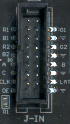
Larger matrixes like mine will also have a “D” input that replaces one of the ground pins. So what do these signals do?
OE – Active low output enable. Set this high to temporarily turn off all the LEDs.
CLK – Clock signal used for shifting color data into the matrix’s internal shift registers.
LAT – When high, data in the shift registers is copied to the LED output registers.
A, B, C (and maybe D) – Selects one of 8 (or 16) rows in the matrix to illuminate.
[R1, G1, B1] – Color data for the top half of the matrix.
[R2, G2, B2] – Color data for the bottom half of the matrix.
A matrix like this one can’t turn on all its LEDs simultaneously – only one row is on at a time. But by cycling through the rows very quickly using the A/B/C inputs, and changing the color data at the same time as selecting a new row, it can fool the eye into seeing a solid 2D image. There’s no built-in support for this row scanning, so the microcontroller that’s generating the matrix inputs must continuously refresh the matrix, cycling through the rows and updating the color data. Any interruption from another calculation or microcontroller task will cause the LED image to flicker or disappear.
Internally the matrix can be imagined as a big shift register (or actually several shift registers in parallel). The shift register size is equal to the matrix’s width. For a 64-wide matrix, the microcontroller shifts in 64 bits of data, generating a positive CLK edge for each bit, and then strobes LAT to load the shift register contents into the LED output register. The LEDs in the currently-selected row then turn on or off, depending on the data that was loaded.
Because each row contains 64 independent red, green, and blue LEDs, three independent shift registers are required. The serial inputs to these shift registers are R1, B1, and G1.
But wait – there’s one more important detail. Internally, a W x H matrix is organized as two independent matrixes of size W x (H / 2), mounted one above the other. These two sub-panels share the same OE, CLK, and LAT control inputs, but have independent color inputs. R1, G1, B1 are the color inputs for the upper sub-panel, and R2, G2, and B2 are for the lower sub-panel.
Putting everything together, we get this recipe for controlling the matrix:
2. Initialize a private row counter N to 0.
3. Set R1,G1,B1 to the desired color for row N, column 0.
4. Set R2,G2,B2 to the desired color for row HEIGHT/2+N, column 0.
5. Set CLK high, then low, to shift in the color bit.
6. Repeat steps 3-5 WIDTH times for the remaining columns.
7. Set OE high to disable the LEDs.
8. Set LAT high, then low, to load the shift register contents into the LED outputs.
9. Set ABC (or ABCD) to the current row number N.
10. Set OE low to re-enable the LEDs.
11. Increment the row counter N.
12. Repeat steps 3-11 HEIGHT/2 times for the remaining rows.
Using this method, each pixel in the matrix is defined by a 3-bit color, supporting the 8 basic colors red, green, blue, cyan, magenta, yellow, black, and white. It’s certainly possible to create more colors by using PWM to alter the duty cycle of the red, green, and blue LEDs, but this quickly becomes complex and too CPU-intensive for your average Arduino. The Adafruit library squeezes out 12-bit 4/4/4 color, but it’s hard-coded for only the Arduino Uno and Mega. I chose to keep my example code simple and skip PWM, so the color palette is limited but it’ll run on any ATMEGA (or really on any generic microcontroller).
This method is appropriate for displaying a static image that was previously drawn into a memory buffer. It won’t work for animated images, because the code for updating the animation would need to be interleaved somehow into the code for refreshing the matrix. If you need animation, you’ll need to perform steps 3-11 inside an interrupt service routine that’s executed at roughly 3200 Hz (or 200 Hz times HEIGHT/2). Anything slower than that, and the human eye will begin to perceive flickering.
Here’s my example code using the above method. It refreshes the matrix as quickly as the CPU allows, and provides a very basic setPixel(x, y, color) API. The code was written for a 16 MHz ATMEGA32U4, but it doesn’t use any ATMEGA-specific hardware features, and should be easily portable to any other microcontroller with at least 2 KB of RAM.
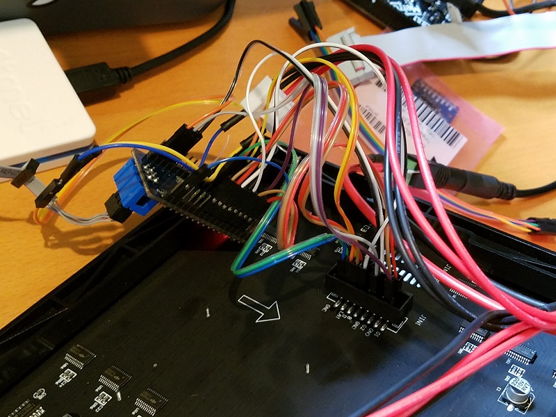
My hardware was an ATMEGA32U4 breakout board, connected to the LED matrix with lots of messy jumper wires (this is Big Mess o’ Wires after all). Fortunately the mess is mostly hidden behind the display, but a custom-made adapter or cable would certainly be cleaner. Here’s a peek at the back side:
I discovered one odd behavior that may be specific to this particular LED matrix: if you don’t cycle through the rows quickly enough, the matrix won’t display anything. It doesn’t work if you set the row number (ABCD inputs) to a fixed value for testing purposes, as I did in my initial tests. It took a huge amount of time for me to discover this, and I haven’t seen this behavior documented anywhere else. From my experiments, if you spend more than about 100 ms without changing the ABCD inputs, the display shuts off. Maybe it’s some kind of safety feature.
Displaying a Bitmap Image
Maybe you’re wondering how I rendered the BMOW logo in the title photo? I certainly didn’t write a bunch of code that calls setPixel() thousands of times – that would be painful. Instead, I used GIMP to export a 64×32 image as a C header file, and then wrote some glue code to parse the data and call setPixel() as needed. Here’s how you can do it too.
First you’ll convert your image to indexed color mode.
2. Select the menu Image->Mode->Indexed.
3. In the conversion dialog, select “Generate Optimum Palette”. Set the maximum number of colors to 256.
4. Click the button “Convert”.
Now you can export the converted image as a C header file.
2. In the save dialog, set the export type to “C source code header (*.h)”
3. Click the button “Export”.
Open the generated header file in a text editor. You should see a section that begins with data like:
static char header_data_cmap[256][3] = {
	{  0,  0,  0},
	{244, 38,117},
	{ 28,239,250},
	...
and a second section that begins like:
static char header_data[] = {
	0,0,0,0,0,0,0,0,0,0,0,0,0,0,0,0,
	3,3,3,3,3,3,3,3,3,3,3,0,0,0,0,0,
	...
For the Arduino or ATMEGA microcontrollers with limited RAM, these declarations must be modified to store the data in program memory (flash ROM) instead of in RAM. Other microcontrollers can skip this step.
For both of the above sections, change static char to const unsigned char, and add PROGMEM just before the = sign:
const unsigned char header_data_cmap[256][3] PROGMEM = { ...

const unsigned char header_data[] PROGMEM = { ...
Then use the function LoadROMImage() to read the bitmap data and set the corresponding pixels in the LED matrix framebuffer. Here’s the updated example code:
led-matrix-bitmap.c
bitmap-data.h
The bitmap data is palettized color, where each palette entry is a color with 8 bits of red, 8 bits of green, and 8 bits of blue. LoadROMImage() just uses the most significant bit of each color channel to select the 3-bit color for the LED matrix framebuffer. If you want something fancier, you could try some kind of error-minimization code for selecting the 3-bit color instead. But if you care strongly about attractive-looking colors, then you should probably use Adafruit’s PWM library or something similar, instead of this code.
Footnote: I struggled to get a good-looking photo of the LED matrix. It’s very bright and sharp, with deeply saturated colors. But regardless of what camera settings I tried for shutter speed, ISO, and white balance, I got a muddy desaturated mess like the photo seen above. Judging by the other photos of this matrix that I found on the web, I’m not the only person to find the photography challenging.
If the example code here was helpful, or you built something interesting using it, please leave me a note in the comments. Thanks!
Read 3 comments and join the conversationMore on Fast Interrupt Handling with Cortex M4
Can a fast microcontroller replace external glue logic, while also continuing to run application code? This is the third in a series of posts considering the question. It’s part of a potential simplification of my Floppy Emu disk emulator hardware, whose present design combines an MCU and a CPLD for glue logic. For readers that haven’t seen the first two parts, you can find them here. Read these first, including the comments discussion after the post body. Go ahead, I’ll wait.
Thoughts on Floppy Emu Redesign
Thoughts on Low Latency Interrupt Handling
There are several pieces of CPLD glue logic that I’m hoping to replace with interrupt handlers on a Cortex M4 microcontroller, specifically the 120 MHz Atmel SAMD51 Cortex M4. The most challenging is a piece of logic that behaves like a 16:1 mux, and must respond within 500 ns to any change on its address inputs. There’s also a write function that behaves a little like a 4-bit latch, as well as some enable logic. I haven’t yet done any real hardware testing, but I’ve spent many hours reading datasheets, writing code, and examining compiler output. I’ll save you the suspense: I don’t think it’s going to work. But it’s close enough to keep it interesting.
Coding an Interrupt Handler
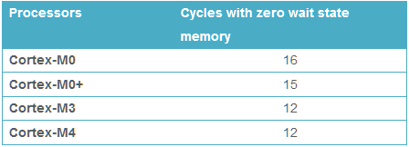
A 120 MHz MCU means there are 120 clock cycles per microsecond. To meet the 500 ns (half a microsecond) timing requirement for the mux logic, the MCU needs to do its work in 60 clock cycles. Cortex M4 has a built-in interrupt latency of 12 clock cycles before the interrupt handler begins to run, so that leaves just 48 clock cycles to do the actual work. At best that’s enough time for 48 instructions. In reality it will be fewer than 48, due to pipeline issues, cache misses, branches, flash memory wait states, and the fact that some instructions just inherently take more than one clock cycle. But 48 is the theoretical upper bound.
I spent a while digging through the heavily-abstracted (or should I say obfuscated) code of Atmel Start, the hardware abstraction library provided for the SAMD51. Peeling back the layers of Start, I wrote a minimal interrupt handler that directly manipulates the MCU configuration registers for maximum speed, rather than using the Start API. I ignored the write latch and the enable logic for the moment, and just wrote an interrupt handler for the 16:1 mux function. Bearing in mind this code has never been run on real hardware, here it is:
volatile uint32_t selectedDriveRegister;
volatile uint32_t driveRegisters[16];

void EIC_Handler(void)
{
	// a shared interrupt handler for changes on five different external pins:

	// EXTINT0 = PA00 = SEL - interrupt on rising or falling edge
	// EXTINT1 = PA01 = PH0 - interrupt on rising or falling edge
	// EXTINT2 = PA02 = PH1 - interrupt on rising or falling edge
	// EXTINT3 = PA03 = PH2 - interrupt on rising or falling edge
	// EXTINT4 = PA04 = PH3 - interrupt on rising edge
	// PA11 = output

	uint32_t flags = EIC->INTFLAG.reg; // a 1 bit means a change was detected on that pin

	// clear EXTINT0-4 flags, if they were set.
	EIC->INTFLAG.reg = (flags & 0x1F); // writing a 1 bit clears the interrupt flags

	// mask the 4 lowest bits and use them as the address of the desired drive register
	selectedDriveRegister = PORT->Group[GPIO_PORTA].IN.reg & 0xF;

	// don't need to check if drive is enabled.
	// output enable will be handled externally in a level shifter.
	switch (selectedDriveRegister)
	{
		case 7:
			// motor tachometer
			// enable peripheral multiplexer selection
			PORT->Group[GPIO_PORTA].PINCFG[11].bit.PMUXEN = 1;
			// choose TIMER/COUNTER1 peripheral
			PORT->Group[GPIO_PORTA].PMUX[11>>1].bit.PMUXO = MUX_PA11E_TC1_WO1;
			break;

		case 8:
			// disk data side 0
			// enable peripheral multiplexer selection
			PORT->Group[GPIO_PORTA].PINCFG[11].bit.PMUXEN = 1;
			// choose SERCOM0 peripheral
			PORT->Group[GPIO_PORTA].PMUX[11>>1].bit.PMUXO = MUX_PA11C_SERCOM0_PAD3;
			// TODO: main loop must check selectedDriveRegister to see if it's 8 or 9 when adding
			// new bytes to SPI
			break;

		case 9:
			// disk data side 1
			// enable peripheral multiplexer selection
			PORT->Group[GPIO_PORTA].PINCFG[11].bit.PMUXEN = 1;
			// choose SERCOM0 peripheral
			PORT->Group[GPIO_PORTA].PMUX[11>>1].bit.PMUXO = MUX_PA11C_SERCOM0_PAD3;
			// TODO: main loop must check selectedDriveRegister to see if it's 8 or 9 when adding
			// new bytes to SPI
			break;

		default:
			// disk state flags and configuration constants
			// disable peripheral multiplexer selection, return to standard GPIO
			PORT->Group[GPIO_PORTA].PINCFG[11].bit.PMUXEN = 0;
			// set the output pin high or low, according to the register state
			if (driveRegisters[selectedDriveRegister])
				PORT->Group[GPIO_PORTA].OUTSET.reg = (1 << 11);
			else
				PORT->Group[GPIO_PORTA].OUTCLR.reg = (1 << 11);
			// TODO: also change the PA11 output in the main loop, if the selected register
			// changes its value
			break;
	}
}
You'll notice that EXTINT4 (the PH3 signal on the disk interface) isn't actually used in this code, but it will be needed later for the write latch.
The default of the switch statement is about what you'd expect: it uses four of the inputs to construct a 4-bit address, then uses that address to access an array of 16 internal drive registers. Then it sets the output pin high or low, depending on the internal register value.
Addresses 7, 8, and 9 get special handling. These aren't really registers, but are pass-throughs of the drive motor tachometer signal or of the instantaneous read head data from the top or bottom of the disk. They're not static values, but rather are constantly changing streams of data. I plan to implement the tachometer using the timer/counter peripheral, and the read head data using the SPI peripheral. All of these functions share the same pin, PA11. The code must enable and disable the peripheral pin remapping functions as needed.
After finishing this speculative interrupt handler code, I compiled it in Atmel Studio, using gcc with -O2 optimization. Then I viewed the .lss to see what code the compiler generated:
00000c70 <EIC_Handler>:
 c70:	481f      	ldr	r0, [pc, #124]	; (cf0 <EIC_Handler+0x80>)
 c72:	4b20      	ldr	r3, [pc, #128]	; (cf4 <EIC_Handler+0x84>)
 c74:	6942      	ldr	r2, [r0, #20]
 c76:	4920      	ldr	r1, [pc, #128]	; (cf8 <EIC_Handler+0x88>)
 c78:	f002 021f 	and.w	r2, r2, #31
 c7c:	6142      	str	r2, [r0, #20]
 c7e:	6a1a      	ldr	r2, [r3, #32]
 c80:	f002 020f 	and.w	r2, r2, #15
 c84:	600a      	str	r2, [r1, #0]
 c86:	680a      	ldr	r2, [r1, #0]
 c88:	2a08      	cmp	r2, #8
 c8a:	d012      	beq.n	cb2 <EIC_Handler+0x42>
 c8c:	2a09      	cmp	r2, #9
 c8e:	d010      	beq.n	cb2 <EIC_Handler+0x42>
 c90:	2a07      	cmp	r2, #7
 c92:	f893 204b 	ldrb.w	r2, [r3, #75]	; 0x4b
 c96:	d01a      	beq.n	cce <EIC_Handler+0x5e>
 c98:	f36f 0200 	bfc	r2, #0, #1
 c9c:	f883 204b 	strb.w	r2, [r3, #75]	; 0x4b
 ca0:	4816      	ldr	r0, [pc, #88]	; (cfc <EIC_Handler+0x8c>)
 ca2:	680a      	ldr	r2, [r1, #0]
 ca4:	f850 2022 	ldr.w	r2, [r0, r2, lsl #2]
 ca8:	b9ea      	cbnz	r2, ce6 <EIC_Handler+0x76>
 caa:	f44f 6200 	mov.w	r2, #2048	; 0x800
 cae:	615a      	str	r2, [r3, #20]
 cb0:	4770      	bx	lr
 cb2:	f893 204b 	ldrb.w	r2, [r3, #75]	; 0x4b
 cb6:	f042 0201 	orr.w	r2, r2, #1
 cba:	f883 204b 	strb.w	r2, [r3, #75]	; 0x4b
 cbe:	f893 2035 	ldrb.w	r2, [r3, #53]	; 0x35
 cc2:	2102      	movs	r1, #2
 cc4:	f361 1207 	bfi	r2, r1, #4, #4
 cc8:	f883 2035 	strb.w	r2, [r3, #53]	; 0x35
 ccc:	4770      	bx	lr
 cce:	f042 0201 	orr.w	r2, r2, #1
 cd2:	f883 204b 	strb.w	r2, [r3, #75]	; 0x4b
 cd6:	f893 2035 	ldrb.w	r2, [r3, #53]	; 0x35
 cda:	2104      	movs	r1, #4
 cdc:	f361 1207 	bfi	r2, r1, #4, #4
 ce0:	f883 2035 	strb.w	r2, [r3, #53]	; 0x35
 ce4:	4770      	bx	lr
 ce6:	f44f 6200 	mov.w	r2, #2048	; 0x800
 cea:	619a      	str	r2, [r3, #24]
 cec:	4770      	bx	lr
 cee:	bf00      	nop
 cf0:	40002800 	.word	0x40002800
 cf4:	41008000 	.word	0x41008000
 cf8:	2000063c 	.word	0x2000063c
 cfc:	200005f8 	.word	0x200005f8
I don't know much about ARM assembly, but I can count 44 instructions. Already that looks pretty dubious for execution in 48 clock cycles. A couple of cache misses, or multi-cycle branches, or anything else that requires more than one clock per instruction, and the interrupt handler will be too slow to work. And if I attempt to add the missing write latch logic, the code will almost certainly be too slow. Even just an if() test to see whether the write latch was written would probably be too much extra code.
Meanwhile the microcontroller will be running the main application, responding to user input, updating the display, and streaming disk data. Occasionally the main loop will need to do an atomic operation, requiring interrupts to be disabled for a few clock cycles. If an external pin changes state during that time, the interrupt handler will be delayed by a few clock cycles.
The interrupt handler shown above is appropriate for one of the Floppy Emu's many disk emulation modes. In other modes, a different behavior is needed. A real interrupt handler would need some more if() checks at the beginning to perform different actions depending on the current emulation mode. This would add a few clock cycles more.
Even reaching this "almost fast enough" level would require some minor heroics. I'm fairly certain the interrupt handler code would need to be in RAM, not flash, to minimize or eliminate flash wait states. Even RAM might not be enough - it might need to be placed in the special "tightly coupled memory" region. The vector table itself probably also needs to be relocated from flash to RAM or TCM. This should be theoretically possible, but it's the sort of uncommon thing that's often difficult to find good documentation or examples about, and that eats up lots of development time.
To make a long story short - it doesn't look like it's going to work. And even if it did work, it might be such a pain in the ass that it negates any gain I'd get by eliminating the CPLD. And yet it looks pretty close to working, at least within a factor of two if not less. If the timing requirement were 1000 ns instead of 500 ns, I think I could make it work.
Other Interrupt Oddities
According to the docs I've read, interrupt handlers on ARM are just like any other function. There's no special interrupt prologue or epilogue, and there's no RTI return from interrupt instruction. And yet gcc does specify an interrupt attribute for ARM functions:
__attribute__ ((interrupt))
The code in Atmel Start doesn't appear to use that attribute for its interrupt handlers. So is it needed or not? What does it do? As best as I can tell, it adds some extra code that aligns the stack pointer upon entry to the interrupt handler, but why? If I add the interrupt attribute to my EIC_Handler(), it gets many instructions longer.
Another unanswered question is how to handle nested interrupts. EIC_Handler wouldn't be the only interrupt handler in the firmware, but it should be the highest priority. If another interrupt handler is running when an external pin changes state, that handler should be pre-empted and EIC_Handler should be started. The Cortex M4 supports nested interrupts, but is there any extra code needed in the interrupt handlers to make it work correctly? Extra registers that must be pushed and popped? I'm not sure, but this discussion suggests the answer is yes. If so, that would add still more instructions to the interrupt handler, making it even slower.
Read 15 comments and join the conversationThoughts on Low Latency Interrupt Handling
How quickly can a modern microcontroller respond to an external interrupt? Is it possible to achieve consistent sub-microsecond response times, so that external glue logic like muxes could be replaced with software instead? That’s the question I raised at the end of my previous post. If it’s possible, then a hypothetical future redesign of the Floppy Emu could be built using a single fast microcontroller, instead of the present design that combines a slower microcontroller and a CPLD for programmable logic.
Defining the Challenge
When Floppy Emu is emulating a 3.5 inch floppy drive, the computer controls it using an interface similar to a 16-entry 1-bit memory. Or 16 1-bit registers. The contents of these registers are mostly status flags, like whether a disk is inserted, the disk is write-protected, or the head is at track 0. But some of the “registers” are actually dynamically changing values, like the instantaneous data bit at the current head position of the rotating disk, or the tachometer signal from the disk’s motor rotation.
Here I’ve renamed the actual signal names on the interface to help make things clearer:
A3..A0 – The memory address
R – The memory output bit (when reading memory)
WE – Write-enable
For reading data, whenever the address bits A3..A0 change, the value of R must be updated within 500ns. It’s like a memory with a 500ns access time. Also whenever a status flag changes, or one of the dynamic values changes, R must be updated if A3..A0 already contains the address of the value that changed.
This is exactly the operation of a 16:1 multiplexor.
For writing data, at a positive edge of WE, the register at address A2..A0 must be written with the bit from A3. WE will remain high for 1000ns before it’s deasserted. Given this design, only eight of the sixteen registers are writable.
These timing requirements and the interface details are taken from this spec for the Apple 1.44MB Superdrive controller chip. The Apple 400K/800K drives may have different timing requirements, but I’m assuming they’re the same, or else more forgiving than the 1.44MB drive requirements.
So the challenge is this: the Floppy Emu microcontroller must respond to reads within 500ns, and to writes within a 1000ns write-enable signal window.
Choosing the Hardware
There are a bazillion microcontroller options, which is great, but also daunting. Some mcus have features that could make them well-suited to this job, like high clock speeds, dual cores, special peripherals, or programmable logic. The choice is also influenced by my desire for a mainstream mcu, with broad availability, good documentation and community support, good development tools, and a positive long-term outlook. This leads me to eliminate some options like the Parallax Propeller and Cypress PSoC.
For this analysis, I’ll assume the microcontroller is an Atmel SAMD51. If I were actually building this hardware now, that’s what I’d probably choose. The SAMD51 is a fairly new 120 MHz ARM Cortex M4 microcontroller, and is like an upgraded version of the popular SAMD21 used in the Arduino Zero. Adafruit had a gushing review of the SAMD51 when it was released last year. It has a nice selection of hardware peripherals, including some programmable logic, and it’s fairly fast, and cheap.
The SAMD51 is a single-core mcu. As we’ll see, it’s unlikely that a second core would help anyway.
SAMD51 Peripherals
An interesting peripheral on the SAMD51 is the Parallel Capture Controller, and it looks perfect for handling writing data. At the edge of an external clock signal (or WE signal in this example), the value on up to 11 other external pins is recorded and stored in a buffer. Then an interrupt is raised, so that software can examine and process the stored value. If necessary, I think it’s also possible to connect the PCC to the DMA controller, so that incoming values are automatically moved to a memory buffer, and there’s no chance of an overrun if the mcu doesn’t process the data quickly enough. This should guarantee that when writing data, no write is ever missed, although the mcu may not necessarily immediately react to the write.
Using the PCC, I think I can check the box for writing data, and assume it will work fine on the SAMD51.
What peripherals might help with reading data? The SAMD51 has an event system, enabling its peripherals to be chained together in custom ways, without any involvement from the CPU core. For example, using the event system, an edge transition on an external pin can trigger an SPI transmission to begin. Or when SPI data is received, it can trigger an external output pin to go low, high, or toggle. It’s very clever, but after looking at the details, I couldn’t see any obvious way to use the event system to handle reading data.
The SAMD51 also has a programmable logic peripheral called the CCL, Configurable Custom Logic. This looks like exactly the right kind of thing to help with reading data, and it is, but there’s simply not enough of it. It’s like an inferior version of one-quarter of a 16v8 PAL. There’s a total of just four LUTs, and each LUT has only three inputs, so it’s quite limited. The linkage between LUTs is also hard-coded, making it difficult to combine multiple LUTs to create more complex functions. The LUT inputs and outputs can be external pins, other LUTs, or certain peripheral ports, but not arbitrary registers or memory locations. In practice I don’t think the CCL can handle reading data for Floppy Emu, although it might help with it in some small way.
After looking at all the hardware peripherals, none of them seem well-suited to handling reading data. The best solution looks like a plain old interrupt. Whenever A3..A0 changes, it will trigger an interrupt, and the interrupt handler code will update R with the new value. Will it be fast enough?
Interrupt Handlers
Here’s some pseudocode for the interrupt handlers. First, handling writing data with the PCC:
PCC_Interrupt_Handler()
{
	registerNumber = (PCC_DATA & 0x07); // get A2..A0
	registerData = (PCC_DATA & 0x08) >> 3; // get A3 data bit

	internalState[registerNumber] = registerData;

	// set status flags here to step track, eject disk, etc.
	// the main loop will do the actual work

	clearInterrupt(PCC);
}
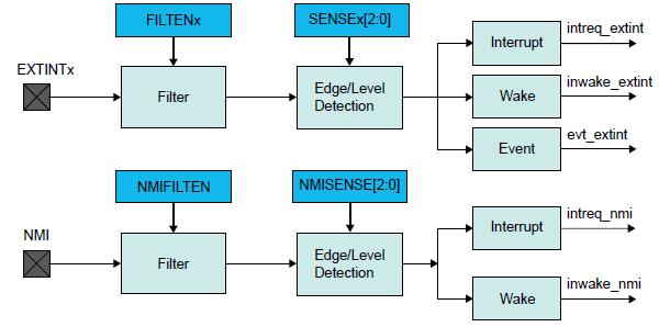
Second, handling reading data with an external pin change interrupt. From my examination of the datasheet, it appears there’s only a single interrupt vector for external interrupts, and the interrupt handler must examine another register to determine which pins actually triggered the interrupt. That means the same handler must not only check the signals described above for reading data, but also other signals that require interrupt handling, like writeRequest (used when the computer writes to the disk) and multiple enable signals (used to select one of several disks that may be present).
bool driveEnabled = false;

EIC_Interrupt_Handler()
{
	if (EIC_INTFLAG & ENABLE_PIN_MASK)
	{
		// enable input has changed
		EIC_INTFLAG &= ~ENABLE_PIN_MASK; // clear interrupt
		driveEnabled = (PIN_STATE & ENABLE_PIN_MASK);
		if (driveEnabled)
			PIN_MODE_OUTPUT_ENABLE |= R_PIN_MASK;
		else
			PIN_MODE_OUTPUT_ENABLE &= ~R_PIN_MASK;
	}

	if (driveEnabled)
	{
		if (EIC_INTFLAG & WRITE_REQUEST_PIN_MASK)
		{
			// writeRequest input has changed
			EIC_INTFLAG &= ~WRITE_REQUEST_PIN_MASK; // clear interrupt
			writeState = (PIN_STATE & WRITE_REQUEST_PIN_MASK);

			// set status flags here to handle beginning and ending
			// of disk sector writes in the main loop
		}

		if (EIC_INTFLAG & ADDR_PINS_MASK)
		{
			// the A3..A0 input pins have changed
			EIC_INTFLAG &= ~ADDR_PINS_MASK; // clear interrupt
			registerNumber = ((PIN_STATE & ADDR_PINS_MASK) >> ADDR_PINS_SHIFT); // get A3..A0

			if (internalState[registerNumber])
				PIN_OUTPUT_VALUE |= R_PIN_MASK; // set R to 1
			else
				PIN_OUTPUT_VALUE &= ~R_PIN_MASK; // set R to 0

			if (registerNumber == INSTANTANEOUS_DISK_DATA_REGISTER)
				PIN_MUX[R_PIN] = PERIPHERAL_SPI;
			else if (registerNumber == MOTOR_TACHOMETER_REGISTER)
				PIN_MUX[R_PIN] = PERIPHERAL_TIMER_COUNTER;
			else
				PIN_MUX[R_PIN] = GPIO;
		}
	}
}
There’s some extra code about enable and write request. For the address, the interrupt handler must also adjust the mcu’s pin mux to control what’s actually driving the output on the R pin. In most cases it’s a GPIO, and the value comes from the internalState[] array and is set in the PIN_OUTPUT register. But for some addresses, the selected value is a dynamically changing quantity that comes from an active SPI peripheral, or a timer/counter peripheral.
Interrupt Priority and Pre-emption
EIC_Interrupt_Handler should be given the highest interrupt priority, higher than interrupts for other events like button pushes or SD card data transfers. With a higher priority, I’m fairly certain the EIC_Interrupt_Handler will interrupt any other interrupt handler that might be running at the time. Isn’t that what’s meant by the “nested” part of the ARM’s nested vector interrupt controller?
What about the PCC_Interrupt_Handler, for writing data? Should it have the same priority, or a lower one? Should reads interrupt writes? Can that ever actually happen? Does it matter? I’m not sure.
Can the EIC_Interrupt_Handler interrupt itself? If A0 changes, and EIC_Interrupt_Handler begins to run, and then A1 changes, will the handler be interrupted by a second invocation of the same handler? I think the answer is no. But what probably happens is that the interrupt flag will be set again, and as soon as EIC_Interrupt_Handler finishes, the interrupt will trigger again and EIC_Interrupt_Handler will run again. That seems inefficient, but it’s probably OK.
Interrupt Timing
Now we come to the critical question: can EIC_Interrupt_Handler respond to changes on A3..A0 with a new value on R within 500ns?
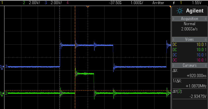
My research suggests the answer is maybe, but it will be difficult. I found two discussion threads where people were attempting to do something similar with Atmel SAM Cortex M4 and M7 microcontrollers. The first used a 300MHz SAME70, and found a 300ns latency to the start of the interrupt handler. The second used a 120 MHz SAM4E and found a 200ns latency to the start of the handler. These are the delays from the input pin transition to when the interrupt handler begins to run, and they don’t include the actual execution time of the interrupt handler, which is probably several hundred nanoseconds more.
Why so slow? First, the Cortex M4 has a built-in interrupt latency of 12 clock cycles. That’s to do whatever the hardware does for interrupt processing – save the execution state, fetch the interrupt vector, and whatever other voodoo is required. At 120 MHz that’s already 100ns gone.
Then the first instruction of the interrupt handler code must be fetched from internal flash memory. At 120 MHz, the flash isn’t fast enough to supply data in a single clock cycle. It requires 5 wait states, so a read from flash memory needs 6 total clock cycles. That’s another 50ns. So even in the theoretical best-case performance, it will still be a minimum of 150ns before the interrupt handler can begin to run. The two real-world examples I mentioned above were slower.
What about these flash wait states? Does it mean that every instruction in the interrupt handler will need 6 clock cycles to load from flash? I don’t understand the details, but the answer is no. There’s some prefetching and caching happening. Also most instructions are 16 bits wide, and the flash has a 128 bit width, so several instructions can be prefetched and cached at the same time. At least for straight line code with no jumps, I’m guessing that the rest of the interrupt handler can run at speeds approaching 1 instruction per clock cycle at 120 MHz. If anybody knows of good reference data for this, please let me know.
If the flash wait states are a major problem, it may be possible to copy the interrupt handler code to RAM and run it from there. I’m assuming the internal RAM has zero wait states, but I might be wrong on that point.
So 150ns before the interrupt handler can begin to run leaves 350ns remaining. That’s 42 clock cycles at 120MHz. So the interrupt handler can be up to 42 instructions long, on its longest execution path? Not quite, because some common instructions like STR require two clock cycles. Assuming an average time of 1.5 clock cycles per instruction, those 42 clock cycles are only enough for 28 instructions. Can EIC_Interrupt_Handler be implemented in only 28 Thumb assembly instructions? Um… maybe?
Complicating Factors
A few other factors raise the difficulty bar further. If the main code ever disables interrupts, or performs any atomic operations, it will delay running of the EIC_Interrupt_Handler and cut further into that 500ns window. In code that uses lots of interrupts, sometimes it’s impossible to avoid needing critical sections where interrupts are briefly disabled, for example to check some value and then set another value based on the first one. Failure to do this can cause rare but serious bugs, if an interrupt intervenes between reading the first value and setting the second.
Another serious complication is the possibility of multiple back-to-back invocations of EIC_Interrupt_Handler. What happens if one of the A3..A0 inputs changes immediately after execution of the line:
registerNumber = ((PIN_STATE & ADDR_PINS_MASK) >> ADDR_PINS_SHIFT); // get A3..A0
The remaining code will output the value of R for the old A3..A0, then the interrupt handler will finish, then a new interrupt will trigger and the handler will be invoked again to process the new A3..A0 input state. The total latency from the change on A3..A0 to the final correct output value of R will be something like 1.5 times the latency for the normal case. In a system where the timing margins are already very tight, that may be enough to break it entirely.
I don’t see any way around this back-to-back invocation problem. Moving EIC_INTFLAG &= ~ADDR_PINS_MASK to the end of EIC_Interrupt_Handler wouldn’t help anything. It would actually clear the pending interrupt flag from the second change of A3..A0 without ever responding to it, resulting in incorrect behavior.
Conclusions
So can this work – is software interrupt processing viable with these kinds of timing requirements? Is there some optimization trick I can use in the interrupt handler to improve things? Should I even spend the time to attempt it? Maybe there’s some clever way to use the built-in CCL programmable logic that I’ve overlooked, to help accelerate the interrupt handler or even replace it entirely? Or should I just write off this idea as too difficult and too problematic, and continue using a separate programmable logic chip for a mux and glue logic? Decisions…
Read 15 comments and join the conversationWhat’s on the BMOW Bookshelf
Over the decades, I’ve pared my collection of books down to just four shelves – only about 100 volumes from a lifetime of reading and studying. Because who needs physical books in an age where everything is available online? The few books that remain in my collection have survived a relentless process of repeated culling, until only the most meaningful and valuable ones remain. Want to take a peek? Here are some selections from the shelves.

Computation Structures, by Ward and Halstead. This was my original digital electronics textbook, covering everything from the transistor to CPU design, and is the only one of my bazillion university textbooks to have survived the cull. This book and MIT’s 6.004 class are what first got me excited about building with electronics. The book is a bit dated now: for something more up-to-date, maybe try Horowitz and Hill instead.

At the end of Computation Structures are schematics and control software for a DIY 8-bit computer called the MAYBE, from which I liberally borrowed ideas for my BMOW 1 computer. I built the MAYBE on a giant breadboard in a suitcase, chip by chip and wire by wire, over a semester-long class.

Practical Electronics for Inventors, by Scherz and Monk. This is a great reference for all those electronics details I should have learned, but didn’t. It puts an emphasis on practical engineering applications, with just enough theory to make sense of it all. When I find myself staring at some Forrest Mims schematic or other inscrutable circuit full of bipolar transistors and passives with unknown purpose, this book is a helpful deciphering aid.

The Black Art of Video Game Console Design, by André LaMothe. Ignore the slightly misleading title. This book is a great how-to guide for designing and building digital electronics projects of all types, with a particular emphasis on microcontroller projects. It covers analog and digital theory, circuit analysis, prototyping techniques, computer architecture, video synthesis, relevant tools, and more. If I could only have a single reference book for all my BMOW projects, this would probably be it.

FPGA Prototyping with Verilog Examples, by Pong P. Chu. For anyone that’s interested in building things with FPGAs or CPLDs, but finds it hard to get past the phase of blinking an LED, check out this book. Verilog can be a difficult language for someone coming from procedural languages like C++. It looks superficially similar, but is actually radically different, with every line of “code” running in parallel. This book goes beyond the Hello World stuff, and provides well-explained examples like a digital stopwatch, a soft UART, PS/2 keyboard IO, and a memory controller. There’s also a VHDL version of this book by the same author, if you prefer that to Verilog.

Macintosh Repair and Upgrade Secrets, by Larry Pina. This book is the bible for vintage Mac collectors. It’s long out of print, but I managed to snag an old copy from eBay. Does you Mac Plus make a “flupping” sound and refuse to turn on? Got an original Mac 128K with floppy drive problems, or video that’s reduced to a single horizontal line? Larry explains how to fix it, pointing to exactly which components need testing and replacement. These were the good old days when hackers could fix their busted motherboard by replacing transistor Q5 with a Radio Shack soldering iron, instead of making an appointment at the Genius Bar.

The New Apple II User’s Guide, by David Finnigan. Unlike Macintosh Repair and Upgrade Secrets, Finnigan’s Apple II bible was published in 2012 and is therefore relatively up to date. It covers all the common repairs for the Apple II family, as well as lots of reference material for collectors who may not have grown up with an Apple II, or forgotten what CALL -151 does. What’s better, it also discusses many of the challenges and options for using an Apple II computer in the 21st century. These include how to get your Apple II on the internet, solid state floppy disk alternatives, archiving tools, and the like.

Web Database Applications with PHP and MySQL. This book is essentially “how to build an interactive web site for dummies” using 2004 technology, so it’s dated now, but I still refer to it occasionally. Even for someone with no plans to build a web site, it’s a good introduction to the concepts of how web sites work under the hood. The book describes the ever-popular LAMP stack (Linux, Apache, MySQL, PHP) used to build the front-end and back-end of web applications. Using the skills learned from this book, augmented with more online learning, I’ve built about a dozen different web sites over the years.

Reversing: Secrets of Reverse Engineering, by Eldad Eilam. This is a fascinating look at how software programs are put together, and how they can be pulled apart and modified. I’m not aware of any other books like this one, which makes it that much more entertaining. Reverse engineering sometimes gets a bad reputation, and some people believe it’s only relevant for defeating copy-protection or other morally questionable purposes. The author introduces other uses, such as dissecting and analyzing malware, or understanding software that lacks source code and documentation. For anyone who enjoyed my post about what happens before main(), or my quest to create the smallest possible Windows executable, I recommend checking out this book.

Compute! Magazine, January 1985. This is the only remaining example of my once-mighty collection of computer magazines. There’s no special significance to this particular issue, other than that it was the only one to escape the recycling bin. It’s always amusing to browse. Loading software from cassette tape? Compuserve ads? And who didn’t love typing in those 20-page long BASIC program listings?

Flatland, by Edwin A. Abbott. This classic 1884 science fiction “romance of many dimensions” will blow your mind in just 92 pages. Imagine you’re a three-dimensional being attempting to explain things to inhabitants of Flatland, a 2D world. Imagine those Flatlanders attempting to explain their world to the miserable inhabitants of 1D Lineland. Now ponder the implications for our own three-dimensional existence: is it any more real than Flatland or Lineland? Where are the 4D visitors to Earth, and what might they look like? It’s a fantastic thought experiment, and the side-plot satire of Victorian society values is a hilarious bonus.

The Monopoly Companion, by Philip Orbanes. If you thought Monopoly was just a silly game for kids, you’re wrong. Back in my university days, my group of friends played many hundreds of Monopoly rounds, arguing strenuously over trading and strategy. A good friend was the Massachusetts champion one year, and represented the state at the National Monopoly Championships held in Atlantic City. The book describes general strategies like a preference for certain color groups (orange is best), and the importance of building to the three house level. We created a detailed software simulation accounting for all board squares, rents, cards, and dice roll probabilities, and ran it millions of times to determine the best strategy. Then we sent a letter to this book’s author, disputing some of his conclusions. God, what a bunch of nerds we were.

Your Money or Your Life, by Dominguez and Robin. We all spend a tremendous amount of time and energy in the attempt to accumulate money, sometimes without really considering why. Yes we need a safe place to live, food to eat, and other necessities – but what then? The money itself won’t bring happiness. Have we really thought about exactly what will bring happiness? How much of our life’s energy are we willing to trade away for those things? Having identified them, might there be other ways to get similar things that require less or no money? Can money even buy them at all? Your Money or Your Life helps guide readers towards a future where they may not be rich in dollars, but are rich in the things they value most.

Finding Your Own North Star, by Martha Beck. Where are we headed? Why? What’s important to our essential self? Like other self-help books or the time-honored What Color is Your Parachute, this book aims to help identify paths that are best-aligned with one’s values. It resonated with me in a way that other similar books didn’t. One clever exercise was to get everybody on your side, by intentionally redefining who “everyone” is. Another was an invitation to envision the best possible personal future imaginable, and map it out. The act of defining a goal already brings it closer.

The Goldfinch, by Donna Tartt. A friend and I read this Pulitzer Prize winning novel at the same time. She thought it was just OK. I thought it was outstanding. It was one of those books that when you finish, you set it gently in your lap and just stare vacantly into space for a long while, trying to digest it all. Tartt’s prose is rich and evocative like a master painting, and her story of loss and disaffection is heartbreaking. But what really moved me was the portrayal of the awkward intimacy of adolescent male friendships, the things said and unsaid but understood, the struggle to carry those relationships into adulthood. I felt Tartt had snooped inside my mind and extracted feelings I didn’t even know were there.

A family bible from 1817. Not many artifacts survived the past two centuries with my family, but this one did. It’s a huge volume with an imposing leather cover, and on the inside leaf are inscribed the births and deaths of generations.

“Joshua Ladd was born 1st mo. 7 1817”. That’s January 7 to us, so Joshua just had his 201st birthday recently. He was my great-great-great-great-grandfather, a farmer originally from Virginia who at age 14 moved to Ohio with his mother and siblings after the death of their father. Ohio had just become a state, and the family moved in search of new opportunities. Joshua opened a grocery and supply store in the town of Westville, near Damascus OH. I still have the wedding gloves of Joshua’s daughter Sarah tucked safely in a box. Any Ladds in your family tree? Maybe we’re related.

Essays by Ralph Waldo Emerson. This particular volume is from 1883, and was passed down through generations to my father and then me. Sometimes I think those Transcendentalist authors like Emerson, Longfellow, and Thoreau had everything figured out in 1870, and we haven’t accomplished much since. “When you were born you were crying and everyone else was smiling. Live your life so at the end, you’re the one who is smiling and everyone else is crying.”
Read 3 comments and join the conversationMeltdown and Spectre Vulnerabilities Explained

This week brought some fascinating news for CPU nerds: the revelation of security vulnerabilities in the basic hardware architecture of many modern processors. The Meltdown and Spectre vulnerabilities affect virtually all modern computers, according to a sensationalist headline at The Register which called them the “worst ever” CPU bugs. Unlike bugs in a specific software program or operating system that can be fixed with a patch, these are fundamental flaws in the very design of the CPU.
What are these vulnerabilities exactly, how do they work, and how are Meltdown and Spectre different from each other? I must have read twenty different news stories without finding a clear answer. The best I could get was that these vulnerabilities somehow involve the CPU’s use of speculative execution: an optimization trick that executes code before it’s known whether the code should really be executed, discarding the results if it’s later determined that the code wasn’t needed. But as a guy who designs custom CPUs as a hobby, I needed a better answer than that. So I started poking beyond the news headlines into the gory tech details.
What follows below is my attempt to explain Meltdown and Spectre to myself, and by extension to readers of this blog. It assumes readers already have some basic knowledge of concepts like CPU internals, caches, and operating systems. But moreso than normal for this blog, I’ll be discussing details that I don’t fully understand myself, and my explanations may be flawed. If you find an error or omission, kindly post a comment and let me know.
Speculative Execution + Caching = Vulnerability
Both Meltdown and Spectre exploit the fact that speculatively executed code can modify the CPU cache. Even if the code is never “really” executed, meaning that it never modifies CPU registers or memory or other processor state, the cache effects of the speculatively executed code can be observed by cleverly-constructed code that follows it, by testing what is and isn’t cached. Consider this example, taken from Google’s Project Zero Blog:
struct array {
  unsigned long length;
  unsigned char data[];
};

struct array *arr1 = ...;
unsigned long untrusted_offset_from_caller = ...;

if (untrusted_offset_from_caller < arr1->length) {
  unsigned char value = arr1->data[untrusted_offset_from_caller];
  ...
}
If arr1->length is not presently in the cache, the CPU won’t immediately know whether the if clause will evaluate true or false. If it guesses true, then the if body will execute speculatively while arr1->length is fetched from main memory. Speculative execution will cause arr1->data[untrusted_offset_from_caller] to be loaded from main memory into the cache. This behavior can be leveraged in several different ways (see below) to gain information about protected regions of memory that are supposed to be private: memory owned by other processes or the kernel. The ability to observe protected memory makes it possible to read passwords, Bitcoin keys, emails, or other sensitive information.
Spectre: Speculative Execution in Branch Prediction
The Spectre vulnerability requires getting the victim (the kernel or another process) to run specially-constructed code, which then leaks information through the cache effects of speculative execution. Consider an expanded version of the previous example.
struct array {
struct array {
  unsigned long length;
  unsigned char data[];
};

struct array *arr1 = ...; /* small array */
struct array *arr2 = ...; /* array of size 0x400 */
unsigned long untrusted_offset_from_caller = ...;

if (untrusted_offset_from_caller < arr1->length) {
  unsigned char value = arr1->data[untrusted_offset_from_caller];
  unsigned long index2 = ((value&1)*0x100)+0x200;
  if (index2 < arr2->length) {
    unsigned char value2 = arr2->data[index2];
  }
}
If arr1->length is not currently in the cache, speculative execution will continue inside the body of the if clause. Either arr2->data[0x200] or arr2->data[0x300] will be fetched from main memory and cached, depending on the least significant bit of arr1->data[untrusted_offset_from_caller]. After the speculative execution has ended, the attacking user mode code can measure how much time is required to load arr2->data[0x200] and arr2->data[0x300]. Whichever one was cached will load faster, revealing whether the LSB of arr1->data[untrusted_offset_from_caller] is 0 or 1. By repeating this process with other bit masks, the attacker can eventually read all of arr1->data[untrusted_offset_from_caller]. And by the choice of untrusted_offset_from_caller, the attacker can read any memory location.
That’s the general idea. Some implementation details and optimization methods are described in the Project Zero blog. The blog also describes another Spectre variant exploiting speculative execution through indirect branches, which I didn’t examine.
How can a user process get the kernel to run this kind of specially-constructed code? It turns out that the Linux kernel has a feature called eBPF that’s designed for this exact purpose, presumably to allow for device drivers or socket filters or other snippets of user-provided code that need to run in the kernel. I’m assuming Windows and Mac OS have something similar. Since running arbitrary user-provided code in the kernel would be a huge security vulnerability itself, eBPF actually runs the code in an interpreter or a JIT engine. But that’s enough to exploit this vulnerability.
Note: after writing this post, I found a second explanation of Spectre from a group of academic researchers working independently from Google Project Zero. Their paper describes Spectre slightly differently, and discusses attacking other processes rather than the kernel. It also includes a proof of concept Javascript attack, in which a malicious bit of Javascript is able to read private memory from the web browser process. Relying on the fact that Javascript is typically JIT compiled to native code, and using debug tools to examine the native output, the authors were able to iteratively tweak the Javascript source code until it produced native code containing an exploitable conditional branch of the kind shown above.
Spectre affects essentially all modern CPUs, given the proper conditions: Intel, AMD, ARM, etc.
Meltdown: Exploiting Out of Order Execution
Meltdown is similar to Spectre, in that they both leak information through the cache from instructions that were never “really” executed. However, with Meltdown there’s no branching involved. The attack relies on the way modern CPUs optimize performance by employing out of order instruction execution. Due to the availability of CPU execution units and dependent data, instructions are sometimes executed in a different order than they appear in a program, but they are retired (registers and state are updated) in order. The fact that they were executed out of order should be invisible to the program, but Meltdown shows that’s not always true. The details are described at cyber.wtf and in a separate academic paper.
When instructions are executed out of order, but aren’t yet retired, their results exist in a kind of limbo that’s very similar to speculatively executed code from branch prediction. However, it’s not clear whether this should properly be called speculative execution. The Meltdown paper refers to these as “transient instructions”, which seems like a good term.
Consider this code:
mov rax, [someKernelAddress]
and rax, 1
mov rbx,[rax+someUserModeAddress]
The first instruction should cause an exception if executed from a user mode process, because it’s an attempt to access kernel memory. However, at least on Intel architectures, it appears that the exception doesn’t occur until the instruction is actually retired. If this code is executing as part of a transient instruction sequence, no exception will yet occur, the privilege violation (bypassing kernel memory protection) will be ignored, and the transient read will succeed. The following transient instructions that use the read value will also succeed, and will affect the cache state in the same way as Spectre, creating a side-channel for leaking information about kernel memory.
Eventually, the first instruction will be retired and the exception will occur. The state changes related to the following instructions will be discarded, because those instructions were never really executed, but their cache side effects will remain. After an exception handler resolves the exception, further code can measure how long it takes to load from address someUserModeAddress vs someUserModeAddress+1, thereby inferring the LSB of someKernelAddress. Further iterations can read the other bits.
To ensure that the Meltdown code sequence executes as an out-of-order transient sequence, the cyber.wtf technique includes a long series of filler instructions ahead of it. These filler instructions all use a different execution unit than the units needed by the Meltdown sequence, and create a long chain of interdependent instructions. So the CPU must sequentially execute the filler instructions one at a time, but meanwhile it can also jump ahead and execute the Meltdown instructions out of order.
Note that “out of order” here refers to the Meltdown code being executed out of order relative to the filler instructions. The Meltdown instructions themselves are executed in order relative to each other, since each one is dependent on the previous one.
At this time, Meltdown appears to be limited to Intel CPUs only. It’s uncertain whether this is due to a fundamental difference in how Intel handles memory protection with respect to out-of-order execution, or is simply due to differences in the size of the reorder buffer between CPU vendors. In a short aside on Meltdown, the Spectre paper states “Meltdown exploits a privilege escalation vulnerability specific to Intel processors, due to which speculatively executed instructions can bypass memory protection.” However, the Meltdown paper reports that the authors were able to observe bypassing of memory protection during out of order execution on ARM and AMD processors too, but were unable to construct a working exploit.
Impact and Mitigation
Both of these vulnerabilities are very bad, enabling user mode code to read other protected memory. However, they’re both local exploits: the attacking code must be running on the machine being attacked, so an attacker must somehow get their code onto your machine first. For this reason, the greatest risk is probably to cloud computing environments, where processes from many different people are running on the same machine, supposedly isolated from one another thanks to memory protection. But there’s also a risk in any situation where one computer runs code received from another, even inside a VM or sandbox.
It’s not clear how Spectre can be fixed in software, because it relies on CPU features that are fundamental to all modern processors. In fact, I don’t think it can be fixed in software – at least not in any general way. One web site says, “as Spectre is not easy to fix, it will haunt us for a long time.” The only good news is that convincing the kernel to run an attacker’s special code with eBPF or other methods isn’t easy. And web browsers can be patched to protect against the sort of Javascript Spectre attacks described in the research paper. But other opportunities for Spectre attacks will remain. Future CPUs may contain hardware fixes for Spectre, but they’ll likely come with a complexity and performance penalty. Maybe cache lines will have to be treated as process-specific data instead of as shared resources.
Meltdown is the more serious of these two vulnerabilities, because it happens entirely in a single user space program and doesn’t require any special code in the victim process or kernel. In the real world, this makes it much easier for an attacker to exploit. Fortunately Meltdown can be fixed at the operating system level, but the fix carries a performance penalty that may be as high as 30%.
In the Meltdown sample code, readers may have wondered how an instruction like mov rax, [someKernelAddress] could possibly work in user mode code, even speculatively, since the kernel uses a different virtual to physical address mapping than the user mode process. It turns out that Linux (and I assume other operating systems too) maps the kernel’s memory into the address space of every user process, for performance reasons. By keeping the kernel permanently mapped, there’s no need to flush the TLB when switching between user and kernel space, and TLB entries for kernel space never need to be flushed. The processor’s MMU can normally be trusted to prevent user processes from accessing this kernel memory – except in the case we’ve just seen. The details are nicely explained in the description of a related technology named KAISER.
The “fix” is KPTI: kernel page table isolation. This ends the longstanding practice of mapping kernel memory into the address space of user processes. This ensures that mov rax, [someKernelAddress] won’t be able to reveal any information. However, it means that the TLB must be flushed every time there’s a switch between user and kernel code. If a user process makes frequent kernel calls, the constant TLB flushing will be expensive and have a significant negative performance impact.
The Future
Meltdown and Spectre are scary, not only because of what they can do themselves, but because they introduce a Pandora’s Box of new vulnerability types we’re sure to see more of in the future. We can no longer think about security analysis as something that gets applied to specific software programs or operating systems, examining the code and imagining it being executed instruction by instruction in an abstract environment. We must now consider the specific highly complex CPU (often not fully documented) that runs this software, and understand the many subtle ways in which the true hardware behavior differs from the instruction-by-instruction conceptual model.
The KAISER document mentions techniques like exploiting timing differences in fault handling, observing the behavior of prefetch instructions, and forcing faults using the Intel TSX (transactional memory) instructions. This will be a new frontier for most developers, forcing them to peel back a layer of abstraction when evaluating future computer security issues. The world just got a lot more complicated.
Read 4 comments and join the conversation