PCB 2.2, Board Tester, And One More Problem

Yellowstone PCB version 2.2 is ready to be sent for fabrication. This is the fourth and hopefully finally PCB version, coming after 1.0, 2.0, and 2.1. But I also thought 2.1 would be the final version, so my powers of prediction are questionable. Here’s what’s new in v2.2:
- Manual -12V Supply Control – I’ve struggled for a while over how to handle the -12V supply on pin 9, which is required for some drives, ignored by others, and causes problems for few. The -12V supply is now enabled by a pair of DIP switches, one for each drive, so the choice is left up to the user. In 99 percent of cases -12V should be ON and the user should never need to touch it. I’ve also added a PTC resettable fuse to each -12V supply connection, which will limit the current to about 30 mA if there’s a misconfiguration.
- /EN3.5 for Drive 2 – The previous version didn’t provide the /EN3.5 signal to Drive 2, since I didn’t think it was needed. That pin was always low (asserted), making 3.5 drives think they were selected, and other types of drives ignore the signal. This worked OK, but it confused the Apple 3.5 Drive A9M0106 into thinking it was connected to a Macintosh, causing it to disable the manual eject button. Version 2.2 resolves this.
- Return of the Disk II Mode Switch – Yellowstone can optionally behave as a vanilla Disk II Controller Card, for maximum compatibility with copy-protected software. PCB version 2.0 enabled this mode with a switch, version 2.1 eliminated the switch in favor of a keyboard enable method, version 2.2 supports both the switch and the keyboard enable.
- Recovery Programming Enable – Version 2.1 supported recovery mode, a method for in-system programming of the FPGA even if it was misprogrammed or erased. Version 2.2 moves the recovery mode enable from a jumper to a DIP switch, since I was already adding a DIP4 package for the other items just mentioned.
- External Programmer Recovery Mode – A Schottky diode was added between the FPGA’s /SPI.CS pin and Yellowstone’s +12V supply. Normally this diode is reverse biased and does nothing, but the forthcoming tester board will be able to dynamically change the +12V supply to 0. This will provide a second way to enable recovery programming mode during manufacturing of Yellowstone boards, avoiding the need to touch the DIP switches and the potential for setting or leaving the switches in the wrong positions.
Tester Board with Blue Pill Brains

I’ve continued sketching out plans for the tester board, as initially described in my previous post. I’ve decided to build the tester around an STM32 Blue Pill, not because the Blue Pill is the absolute best tool for the job, but because it’s an adequate tool and also a helpful gateway to learning more about STM32 development.
The tester board will need a large number of I/Os. After a few hours of sketching, I think a microcontroller with 32 GPIOs will be enough, combined with a pile of port expander hardware. Not coincidentally, 32 GPIOs is exactly the number provided by the Blue Pill. If I get partway through the tester board design and discover that I need an extra I/O pin or two, it could be awkward. It looks like the two serial debug pins can be repurposed as GPIO if you’re not using them, as well as the BOOT1 pin, so it could possibly stretch as far as 35 GPIOs.
The basic design is this: Eight microcontroller pins are used for output, and are connected to four ‘373 transparent latches, providing a total of 32 controllable outputs. Eight pins are used for input, and are connected to four ‘244 buffers, providing a total of 32 inputs. Eight pins are used for bidirectional data bus communication, and the final eight pins are SPI and control signals for the buffers and latches.
During the course of testing, some inputs may also need to be pulled low. A ‘156 decoder will be used for this. The ‘156 can pull low any one of its eight outputs, using a three-bit selection input and an enable input.
One half of a second ‘156 decoder will be used to enable the desired input buffer from among the four possible buffers. Since a buffer is always enabled, this only requires two bits for the selection input, instead of four individual enable signals. This cuts down the number of control signals required from the microcontroller.
The design and programming of the Yellowstone tester board will be a significant engineering challenge in its own right. The proposed approach will require the STM32 Blue Pill mounted on a board with ten other support chips, three connectors, and close to 100 signals. Writing the code to program the FPGA and run/analyze the test vectors will be interesting. Kudos to people who design test fixtures for a living – this stuff isn’t glamorous, but it’s important to get right.
One More Problem – GS/OS and Drive 2

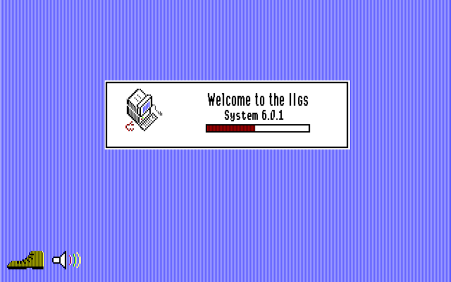
Yellowstone still has many smaller bugs and issues, but as far as I know there’s only one remaining major problem. It’s not even a Yellowstone problem per se, but it affects Yellowstone negatively. The issue is that GS/OS will not boot from Drive 2. It starts to boot, but then early in the boot process it unexpectedly tries to switch to Drive 1, and fails with the error “Unable to load START.GS.OS file”. As far as I can tell, this is a software limitation with GS/OS and not anything that Yellowstone is doing wrong. It shows the same behavior if GS/OS is loading from a 3.5 inch drive or from a Smartport hard disk.
Most other 3.5 inch and Smartport disk controllers will not even try to boot from Drive 2, which may explain why this GS/OS limitation isn’t well-known.
This behavior is similar to some 5.25 inch disk software that refuses to boot from Drive 2, even though there’s no technical reason for it. Such software is written with the assumption that the disk is in Drive 1, and fails if that’s not true. Bad programmer, no biscuit!
You may wonder why this is important. Can’t people just boot GS/OS from Drive 1? Yes they can, but that raises a new problem.
People who run GS/OS are probably booting it from some type of hard drive. If they’re using a Yellowstone card, that means a Smartport hard drive like Floppy Emu’s Smartport HD mode. But occasionally people will want to boot from a 3.5 inch or 5.25 inch disk instead, and they won’t want to unplug and reconnect drives in order to do this. Ideally they could connect a 3.5 or 5.25 inch drive to Yellowstone’s port 1, and a Smartport hard drive to port 2. Since D1 has boot priority, the computer would boot from D1 if there’s a disk there, otherwise it would fall back to booting GS/OS from D2. But since GS/OS won’t boot from D2, this setup isn’t possible.
I’m not sure there’s any great solution to this problem. A second Yellowstone card could do the job, but that’s not ideal. Possibly Yellowstone could show some virtual slot behavior, and act like two cards in different slots. But given my limited understanding of the UDC ROM code on which it’s based, and its overall brittleness and difficulty of making changes, this probably isn’t feasible.
The best idea I’ve come up with is logically swapping the drives, while leaving the physical connections unchanged. Users can attach a Smartport hard disk with GS/OS to Yellowstone’s port 1, and a 3.5 or 5.25 inch drive to port 2, and the computer will always boot from GS/OS on D1. But if a keyboard key is pressed during power-up, drives 1 and 2 will be logically swapped. The 3.5 or 5.25 inch drive on port 2 will behave as D1, and the computer will boot from a disk in that drive. It may be slightly confusing, but I think it will work and will provide maximum flexibility.
Read 5 comments and join the conversation5 Comments so far
Leave a reply. For customer support issues, please use the Customer Support link instead of writing comments.


The GS/OS issue is surely fixable now that you’ve identified it. Someone has released GS/OS 6.0.2-6.0.4 the past few years, so perhaps they can address it?
I’ve tried to figure out who’s behind it yet all the release notes have no contact info. Maybe reach out on Twitter to @jbrooksbsi (who resurrected ProDOS) and/or @a2_4am; maybe they will know and be able to assist contacting the GS/OS dev.
Steve,
You’re one thorough damn guy. Your methodology throughout this entire Yellowstone project should be a case study for guys tasked with solving complex problems.
Great work. Your persistence is particularly commendable.
Steve,
You should consider an STM32F4xx board like this:
https://www.amazon.com/HiLetgo-STM32F407VET6-Cortex-M4-Development-NRF2410/dp/B071KBZR58/ref=sr_1_6?dchild=1&keywords=stm32f4&qid=1629724821&sr=8-6
Much more CPU horsepower & a lot more GPIO. The ST Nucleo-64 boards would be a good choice, too.
Keep up the good work!
I know it seems silly, but the STM32 modules with pre-soldered male pins on the top side will be difficult to incorporate into a second PCB. The tester board will probably be a lot larger than the STM32 module, so the tester board needs to go on the bottom of the STM32 rather than on top. There are some STM32F4 modules with pins on the bottom, or with no pins, but they aren’t very common. More CPU horsepower isn’t really an issue here, but more GPIO would be nice. Blue Pill seems like the path of least resistance, but that may change as I get further into the tester design.
There is probably a good reason why GS/OS only boots off drive 1, the boot code likely only has to keep track of the slot number. START.GS.OS is relatively early in the boot cycle, so the problem is likely in the PRODOS stub loader. Antoine Vignau of Brutal Deluxe would be a good contact regarding the GS/OS boot process.