RAM Test
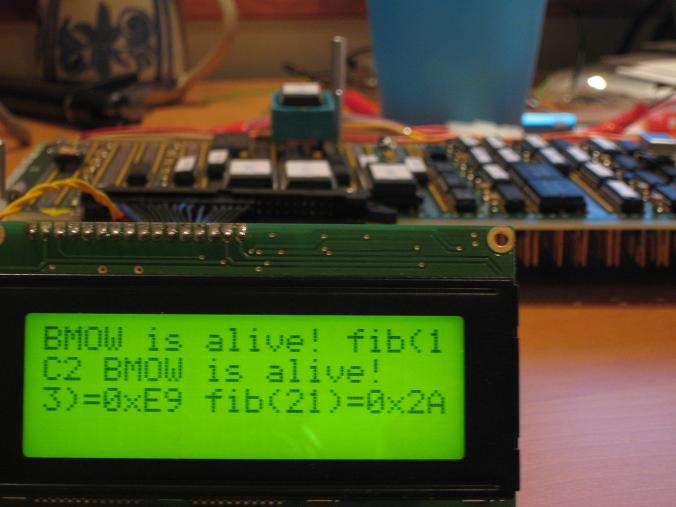
Egads! The RAM works. This thing is starting to look like a real computer now. I wrote an improved version of my fibonacci program that operates on 16-bit values, using 4 bytes of RAM as temporary storage. I then created a super-program by combining the 16-bit RAM-based fibonacci with my earlier 8-bit fibonacci that uses only the A, X, and Y registers, as well as the “BMOW is alive!” program. At bootup, the super-program checks the value in the A register and uses it to choose one of the three demo programs to run. Each demo program writes a new value into A before halting. Since A isn’t cleared when the machine is reset, every time I hit the reset switch it runs the next program in the demo loop. Woohoo, user interactivity! Here’s a photo after running all three:

I’m using the 20×4 LCD now instead of the 16×2 one from the earlier photos. The fibonacci results are written in hexadecimal, since it was easiest for me to generate. The text is a little hard to interpret, because the LCD is mapped as two logical lines, where the first logical line covers the first and third physical lines of the LCD, and the second logical line covers the second and fourth physical lines. It reads “BMOW is alive! fib(13)=0xE9 fib(21)=0x2AC2 BMOW is alive!”
Some system facts:
- Current clock speed is 1MHz. It should be able to go faster ultimately.
- 512 KBytes of RAM, 16 KBytes of ROM.
- Power draw is 8 Watts, implying 1.6A at 5V.
- There are presently 704 connecting wires, so 1408 individual wire wraps.
It’s been a while since I posted any photos of the overall construction progress, so an update is overdue.

Here’s a close-up of the wire-wrap side of the board. Things are getting a little crazy. The photo doesn’t do justice to the fine detail of the dense wiring. Wires are stacked 10 deep in some channels! Big Mess o’ Wires indeed.

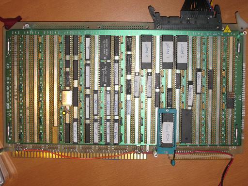
The component side is well-populated now. Eventually the rest of the bottom and right side of the board will be filled. The left side will be available for any possible future expansion, like audio or video.

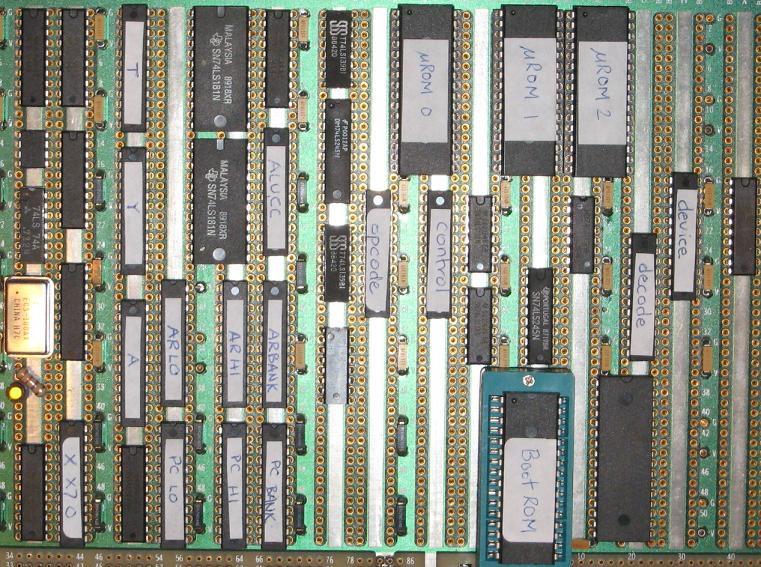
Here you can see the three micro-ROMs at the top, and boot/program ROM below. That’s the newly-installed RAM immediately to the right of the boot ROM. All of the narrow chips with white labels are GALs. The rest of the unmarked chips are various 74LS series logic parts. Since there’s no fan or other moving parts to make an obvious noise, I added the yellow LED below the clock oscillator to remind me when BMOW is on.
Read 2 comments and join the conversation2 Comments so far
Leave a reply. For customer support issues, please use the Customer Support link instead of writing comments.


Wow, this is coming along really fast! Nice job!
I love your great job really.
btw, I have a question and I need your help..
I found mizar vme 7000 wire wrap board. I wonder .. the pins aren’t gold. strange logics are built-in. is that board useful for ttl cpu work?
please check the url of that board. and I hope your advance.
http://cgi.ebay.com/Unused-Mizar-Proto-7000-VME-Wirewrap-Bread-Board_W0QQitemZ120180932609QQcmdZViewItemQQptZCOMP_EN_Workstations?_trksid=p3286.m20.l1116