Funny Fanout Flaws
Ugh, I’ve run into my first design flaw. Fortunately, I don’t think it will be too difficult to fix, but it’s an eye opener nonetheless.
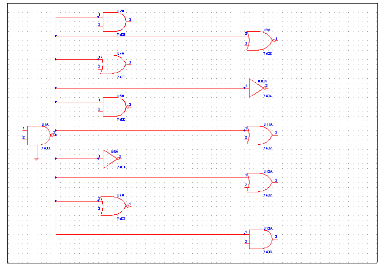
The issue I’m facing is fanout limitations. Fanout is the number of inputs that are connected to an output. Say I’ve got a chip that outputs some data signal, and that signal is passed as an input to ten other chips, then I’ve got a fanout of 10.

So what’s this about fanout limitations? Can’t you connect as many inputs as you’d like to that data ouput? To understand fanout limitations, it’s necessary to leave the cozy digital world of zeros and ones, and consider the analog nature of the circuit. In the case of a logical “1” at the data output, the output chip attempts to bring the output pin to 5 volts, or something close to it. A small amount of current then flows from the output pin to the input pins. In the case of TTL logic (the 7400 family), as long as the voltage at each input pin is over about 2.4 volts, the input chip will treat it as a logical 1. This allows for a certain amount of loss or noise in the circuit between the output and inputs.
Unfortunately, there is always a small amount of internal resistance in the output chip, between the power supply and the output pin, of something on the order of 10K ohms. Let’s say that an input pin draws 20 uA of current, so from Ohm’s law, V = IR, we can calculate an expected voltage drop of 10KOhm * 20uA = 0.2 volts. So with one input connected, the voltage at the output pin won’t actually be 5 volts, it will be 5 – 0.2 = 4.8 volts. As more inputs are connected, the current will increase, and so will the magnitude of the drop below 5 volts. At some point, if enough inputs are connected, the output voltage will sag below the 2.4v threshold needed for a valid logical “1”, and the circuit will stop functioning correctly.
In reality the situation is somewhat more complicated than I’ve described, as the input resistance needs to be considered too, and in fact TTL outputs never drive all the way to 5 volts anyway due to their design. However, the basic conclusion remains the same: connect too many inputs to a single output, and things will go bad. For TTL logic, the generally accepted limit is 10, although it varies from chip to chip.
Examining my schematics, I realized that they call for 10 different chips connected to my memory data bus, and I plan to add one or two more before the project’s completion. That translates to a fanout of 9 to 11 for each of the bus’ data lines. Maybe that would work fine, maybe not, but I don’t really want to find out. With my luck it would kind of work, some of the time, and I’d never be able to figure out what was going on.
My plan for reducing fanout on the memory data bus is to connect all the “write-only” chips (opcode, LCD, and eventually sound and video) to a 74LS244 bus driver, and then connect that driver to the main memory data bus. That will bring the fanout down to 8, even in the worst case if I do add those extra chips. Isolating the read-only and read-write chips should be possible too if it proves necessary, but it would involve using some glue logic to combine various output enable signals, and bidirectional bus-drivers, and other headaches I’d just as soon avoid if I can.
Be the first to comment!No comments yet. Be the first.
Leave a reply. For customer support issues, please use the Customer Support link instead of writing comments.

