Bit by Bit
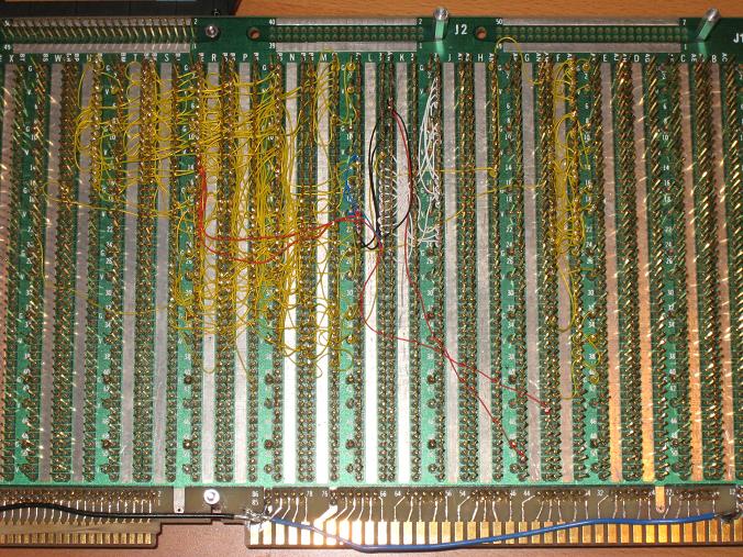
Although progress continues to be slow, the machine is taking shape bit by bit. I bought another 100 foot spool of wire, along with 1000 pre-cut and pre-stripped wires in lengths from 1 to 4 inches. The pre-cut wire makes the job go considerably faster, not only because it saves me from cutting and stripping, but also because consistent length wires are easier to wrap and bend into place on the board.

Big Mess o’ Wires is finally starting to live up to its name! Just look at that mess. My first spool of wire was yellow, and all of the clock and control system connections used the yellow wire. The pre-cut wire I’m using now is a different color for each length: white is 2 inches, black is 2.5 inches, and so on. That gives the board a multi-colored appearance that looks like a mess, but is actually easier to navigate visually than a uniform field of yellow.
The /DRALU problems seem to be gone, now that I’ve made the connections between the ALU system and control system, meaning there are no more floating inputs on the control ROMs. I tested everything out with the logic analyzer again, and it seems OK, although there’s still not much to test with this half-built machine.
At this point, the clock/reset, control, and ALU systems are complete, and I’m getting close to the point where this pile of chips and wires may be able to do something interesting. My next steps will be to add the program ROM, address decoder, program counter, and a few related buffers, and see if I can execute a series of opcodes from the program ROM. Assuming that much works, I’ll add one or two of the registers, and primitive computing should then be possible.
Read 3 comments and join the conversation3 Comments so far
Leave a reply. For customer support issues, please use the Customer Support link instead of writing comments.


Hey, I’m a BEAM robot builder and game programmer, and am interested in building a computer too. I’m going to build a simple adder first, and maybe than move on to pong, or a homebrew. Couple questions:
How exactly did you go about designing this whole thing? What was the solution you had in mind? Were you thinking of a certain function, etc?
I’ve read up on some homebrew stuff, but I can’t really see waht the exact function of these are. Are these pretty much built to be like a microcontroller, ie: Programmable?
With an adder, how might I go about outputting the stuff to a 7-segment?
Thanks!
Hi Brandon!
The “about BMOW” page may answer some of your questions, or shoot me an email and I’ll be glad to tell you more. I did a few digital logic projects in college, so I had some background to start with, although it was 15 years ago. The BMOW design was based on ideas from several other custom computers, especially MAYBE (from the textbook Computation Structures, by Ward and Halstead) and Magic-1 (www.homebrewcpu.com).
Basically, you just need to reason out what parts a computer needs. There needs to be a program, so you need a ROM or RAM to store it. Then you need a program counter (PC) to remember the address of the current program instruction in ROM/RAM. You’ll also need some place to store data, so presumably you’ll want a few data registers. Then you need some way to do math and logical operations: an ALU. Finally, you need some way to generate all the control signals necessary to coordinate all the other components, and enable each one at the appropriate time. You can do this with custom logic to turn the current program instruction into control signals, or you can use microcode (what I did), so each program instruction is itself implemented as microprogram, which is just a sequence of control signals.
My goal was to build a fully functional computer, with a custom CPU at its heart. When it’s finished, it should be something vaguely like an Apple II or Commodore 64, but with text-only output. (Maybe I’ll get the sound and video too someday.) Why do this? I guess I thought it would be an interesting project.
Outputting a 4-bit value to a 7-segment LED is one of those things that’s more complicated than it seems. The 7-segment package has one input pin for each LED segment, so you need some intermediate logic that determines which LEDs to turn on depending on the adder value. For example, the top LED should be on if the value is 0, 2, 3, 5, 6, 7, 8, 9, A, C, E, or F, based on the shape of those numerals. You can construct the necessary logic out of a bunch of AND and OR gates, or use a GAL (I posted on this a while back). For a first project, it might be easier to just use 4 discrete LEDs instead of a 7-segment display, and then read the value as a 4-bit binary number.
OK, I’ll hit you up on email. Thanks for the answers so far! Helpful.