Schematics
I’ve started creating schematics for the machine, using an evaluation version of CSiEDA 5. Making a real schematic that shows all the parts, pins, and interconnections is amazingly time-consuming, but it’s essential if I want to avoid making construction mistakes.

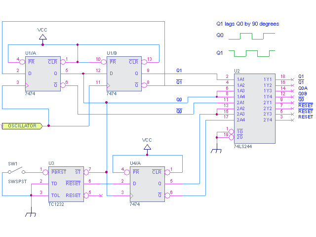
It took me a couple of hours to get familiar with CSiEDA and create this schematic for the clock and reset generation circuitry. A crystal oscillator is used to clock a pair of flip-flops, wired so as to produce two new clock signals, Q0 and Q1, at a quarter the frequency of the oscillator input. Q0 is the primary clock signal, and is used by most other clocked components in the system. Q1 lags Q0 by 90 degrees (one-quarter of a cycle), which is useful for generating other timing signals. The clock signals are buffered by a 74LS244, which has a higher drive current than most TTL chips, meaning each output pin can drive up to 16 other TTL inputs. Some signals appear on multiple ‘244 output pins, where I expect to need them at more than 16 inputs elsewhere in the system.
A Microchip TC1232 supervisor chip is used to generate the /RESET signal. Whenever the +5V input to the TC1232 is too low (during power-on, power-off, or power glitches), it forces the /RESET signal active for about 100ms, restoring the machine to its initial state. It also has an input for a reset switch, with built-in pull-up resistor and debouncing circuitry. The /RESET signal is clocked through another flip-flop, so the rest of the system will only see /RESET change at a clock edge, rather than in the middle of a clock cycle.The TC1232 also has a “watchdog” feature that can be used to auto-reset the machine if it crashes. The CPU is expected to toggle the TC1232’s strobe (/ST) input periodically to indicate that it’s still alive. If too much time passes without /ST being toggled, the TC1232 will force the /RESET signal active. I don’t plan to use this feature, so I’ve tied /ST directly to the clock signal, so it will always be toggling.In the final implementation, the flip-flops and 74LS244 may all be replaced by a single GAL, but the functionality will remain the same.
Read 2 comments and join the conversation2 Comments so far
Leave a reply. For customer support issues, please use the Customer Support link instead of writing comments.


Aren’t Q0 and Q1 at a quarter of the frequency of the oscillator here?
Yes, you’re right. I corrected the text.