

Archive for November, 2021
Call For Yellowstone Beta Testers
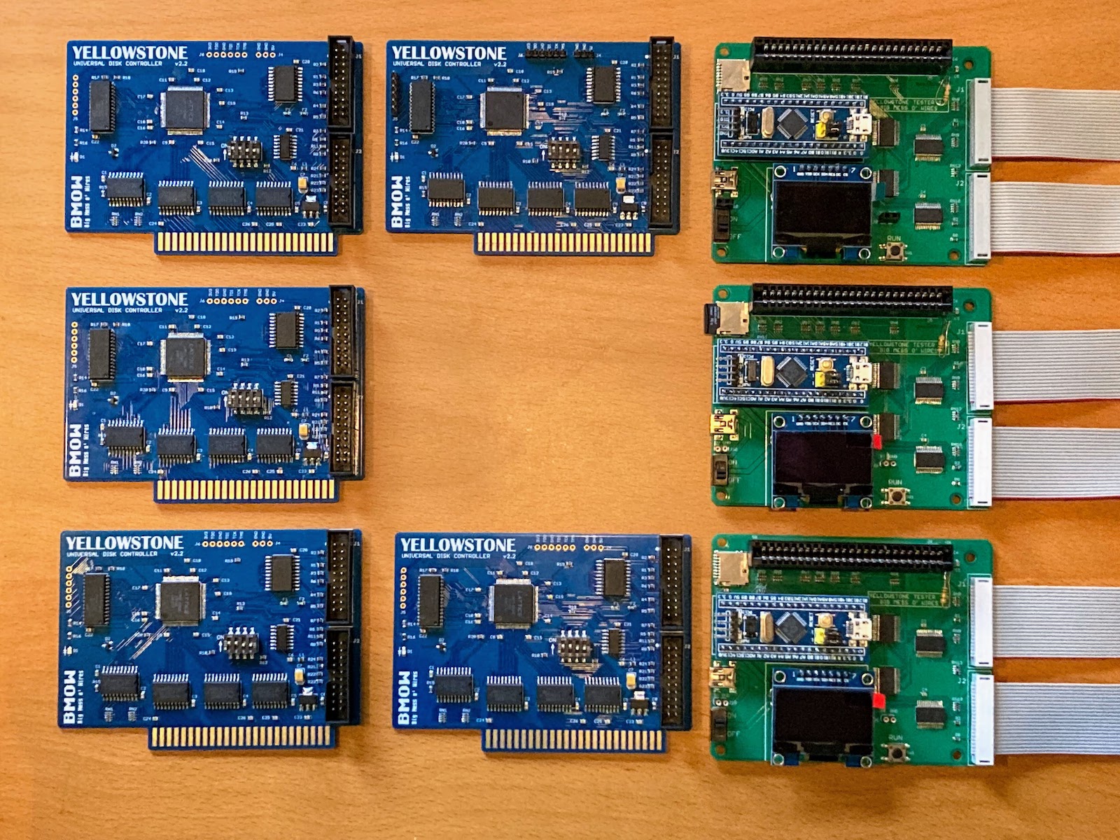
Here we go! Beta testing kicks off today for the Yellowstone universal disk controller for Apple II. Yellowstone is a replacement for the Liron disk controller, the Apple 3.5 disk controller, and the standard Disk II controller, all rolled into one. It even handles Macintosh disk drives. After a soldering marathon this week, I now have five working Yellowstone boards and three working Yellowstone testers. All the testers work with all the boards. The ducks are finally in a row. Let’s do this.
Before jumping into beta testing specifics, some readers may be curious to know how the Yellowstone tester turned out. The goal of the tester is to program and verify a newly-assembled Yellowstone board, as quickly and easily as possible, without requiring any other equipment. The tester development proved to be a major project in its own right, and occupied most of my available time for the past couple of months, but I’m happy to say it’s finally working. Here’s a video demonstrating the tester operation:
Calling Beta Testers
I need your help! I’ve tested the hell out of Yellowstone, but I won’t be truly confident it’s ready until it’s passed through other people’s hands, with other types of computers and disk drives, and other software environments. That’s where you come in.
The ideal Yellowstone beta tester will have:
- at least 5-10 hours available for testing in the next two weeks
- a personality that enjoys making lists, spreadsheets, and similar record-keeping
- a variety of Apple II computers and disk drives, especially an Apple II+, Duo Disk, Unidisk 5.25, Apple SuperDrive (FDHD Drive G7287), third-party 3.5 inch drives from Applied Engineering / Chinon / Laser / American Micro Research, and CPU accelerator cards.
I need to be slightly picky about who gets these beta cards, since I only have a few of them. The cards should go to people who are in the best position to help with testing, either by virtue of the hardware they have or the energy they’re willing to put into methodical testing. If this appeals to you, please get in touch with me using the Contact link at upper-right of the page, and let’s talk! If you’re more interested in Yellowstone for personal use and you aren’t sure you’ll have time or energy for beta testing, you’ll have an opportunity to get one soon when they become generally available.
What You’ll Get
The draft instruction manual for Yellowstone offers a good overview of its capabilities. In brief, any type of Apple II or Macintosh floppy drive from the 1970s – 1990s should work with Yellowstone, as well as intelligent Smartport-based hard disks such as Floppy Emu’s Smartport HD emulation mode. It supports two drives of different types connected at the same time, or up to five drives for intelligent Smartport devices. Drives with 19-pin D-SUB DB-19 connectors and 20-pin rectangular connectors are both supported.
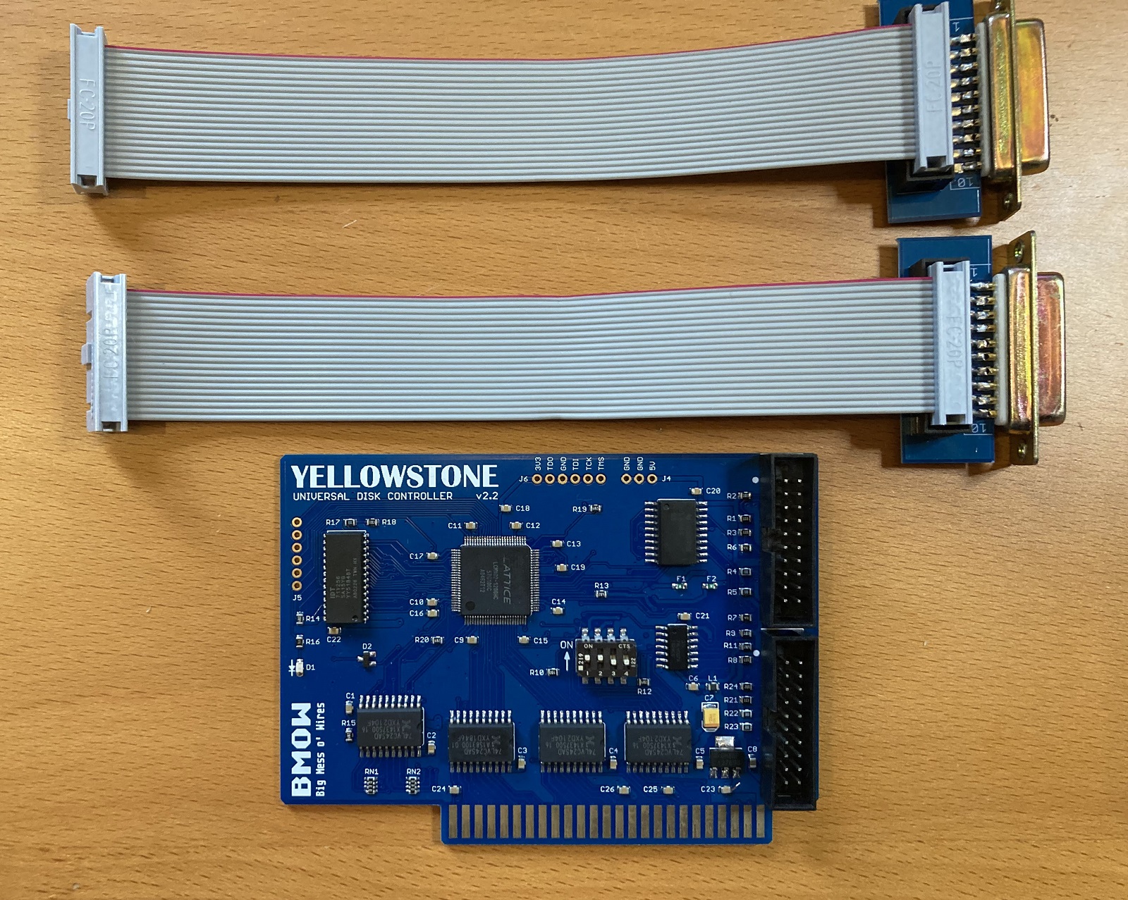
For the beta testers, I will also be including a pair of DB-19 female adapters. These will probably be a separate accessory when Yellowstone goes on sale, since not everyone will need them, and the DB-19 female connectors are rare and somewhat expensive. You’ll need these DB-19F adapters when connecting drives like the Duo Disk, Apple 3.5, or Macintosh M0131. The adapters aren’t needed when connecting a Floppy Emu, a Disk II, or internal / bare drive mechanisms using a ribbon cable with a 20-pin rectangular connector. The wiring of the DB-19F adapters is designed only for use with Yellowstone, so don’t try to connect them anywhere else.
I think that’s everything, and I’m very excited to be launching the Yellowstone beta today. Thanks in advance for your help, and don’t hesitate to contact me if you’re interested in being a beta tester.
Read 9 comments and join the conversationROM-inator Resurrections
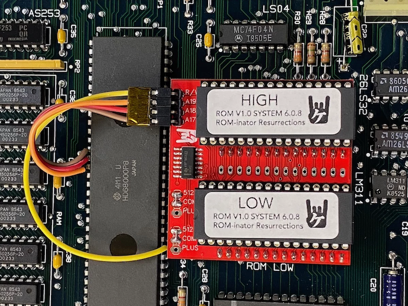
Good news! Kay Koba at Kero’s Mac Mods store is now selling pre-packaged ROM-inator kits for the Macintosh Plus, Mac 512Ke, 512K, and 128K. This is a recreation of the original Mac ROM-inator kit that I designed in 2015. The design is open source, and Kay’s new version is called “ROM-inator Resurrections”.
The ROM-inator replaces the stock 64K or 128K of ROM in a compact Macintosh with a full 1 MB of flash memory. Once installed, the flash ROM’s contents can be updated via software from within the running Macintosh, allowing for extensive customization. The replacement ROM adds a bootable ROM disk to your Macintosh, provides built-in HD20 disk support, replaces the startup sound, changes the Happy Mac icon, and makes it possible to edit the ROM disk or even tweak the ROM toolbox code code.
- Startup beep is replaced by a glass “ping”
- Happy Mac icon is replaced by a Mac wearing sunglasses
- Pirate icon is displayed while waiting to load the ROM disk
- ROM disk image including System 6, Mac Write, Mac Draft, and eight games
- 128K ROM code turns a Mac 128K or 512K into a 128Ke or 512Ke
The ROM-inator is a descendant of Rob Braun’s original Mac Plus ROM Adapter and disk driver. More details about its inspiration and development are here.
When first powered on, the Macintosh will play a customized startup sound, and display a “pirate Macintosh” icon. To boot from the ROM disk, press and hold the R key on the keyboard for a few seconds. If R is not pressed, the Macintosh will boot normally from an attached SCSI disk, or wait for a floppy disk to be inserted.

The utility program Flash Tool can update the flash ROM from within the running Mac. Alternatively, the flash chips can be removed from their sockets and reprogrammed using a standard EPROM programmer.

You can buy a ROM-inator Resurrections kit from Kero’s Mac Mods store. Please refer to their store with any questions or tech support needs; BMOW does not provide any support for these.
Happy ROM hacking!
Read 1 comment and join the conversationZener Regulator Trouble
In my attempts to resolve some logic level problems with the Yellowstone Tester, I decided to take a crude approach, and reduce the 5V supply to about 4.7V using a simple zener diode voltage regulator. From my previous tests with a variable voltage supply, the reduced voltage at 4.7V was enough to get the tester working nicely. But now when I try combining a fixed 5V supply with a resistor and a 4.7V zener, I find that it doesn’t work as expected. Zener regulators apparently don’t behave the way I thought they did, and for this specific circuit, they may not work at all.
The problem is that the rated voltage of a zener diode is only valid for a specific level of current. I knew this, but I thought the voltage would only change a small amount over a wide range of current: perhaps 100 mV of change for the 10 mA to 100 mA range where my circuit operates. In other words, I thought the IV curve for the zener would be very steep, nearly a vertical line.
This proved to be a bad assumption. Using a 1N4732A zener, at a current of 90 mA I do see 4.7V on the zener, but the voltage is only 4.506V at 40 mA, 4.459V at 30 mA, 4.335V at 20 mA, and 4.212V at 10 mA. That’s not good. It’s non-linear, but if it were a resistor then its value would be about 6.1 ohms. I’m not sure how I was meant to know this from the datasheet, which doesn’t include any IV curves. The datasheet does include a dynamic resistance (impedance?) number, but I thought that was for AC applications since it’s specified for a frequency of 1 kHz.
Voltage Regulator Says What?
So how are you supposed to build a voltage regulator using a zener with this amount voltage of variability? The standard way to build a zener regulator is with a resistor in series with a zener, and a load in parallel with the zener:
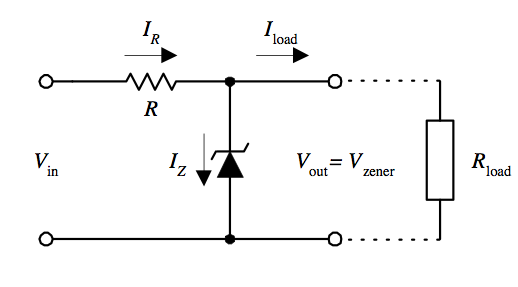
If Vout is ever higher than VZ, then the zener will pass more current, which also increases the current through the resistor, which increases the voltage drop across the resistor and lowers Vout. So Vout gets “regulated” to the value of VZ, so long as the current through the zener remains constant.
If the circuit has a fixed load, then the value of the resistor can be chosen to get the desired current through the zener to achieve the nominal zener voltage. But if the circuit has a variable load, there’s a problem. In order to maintain a regulated output voltage, the voltage drop across the resistor must remain unchanged while the load current changes. That means the current through the resistor must also remain unchanged. The only thing that will change is how much current flows through the load and how much flows through the zener. If the load draws less current, then the zener must draw more, in order to keep the total current constant.
Let’s say the load current can vary between 10 and 100 mA, and the zener can theoretically handle 150 mA before it burns up. For safety’s sake you probably don’t want to push the zener all the way to 150 mA though, so you might limit it to 120 mA. You could choose a resistor value to achieve a constant current of 130 mA through the resistor, which can be divided between the zener and the load 120/10 mA for light loads anywhere up to 30/100 mA for heavy loads. That’s a 90 mA range of currents through the zener, so for a 6.1 ohm equivalent resistance you would see a 0.549V change in the output voltage. That’s not very well regulated at all.
If I’ve analyzed this all correctly, then a zener voltage regulator basically doesn’t work unless the load current never varies by more than about 10 to 20 mA. That’s a pretty lousy regulator. I’m not sure how I never realized this about zener regulators before.
Plan C
So now what? I still need to get the Yellowstone Tester working. The original 5V circuit has problems with the logic levels, and Plan B for reducing the supply voltage to 4.7V with a zener seemingly doesn’t work either. Would I be better off with a simple Schottky diode in series with the 5V supply input? This wouldn’t be perfect either, since the nominal 5V supply might actually be closer to 5.1V or 4.9V, and the voltage drop across the diode will change with the load current. But I still think it would be enough to keep the voltage within a range of about 4.8V to 4.5V, which is better than I’ll get with the zener.
Read 7 comments and join the conversation