

Testing Yellowstone 2.0
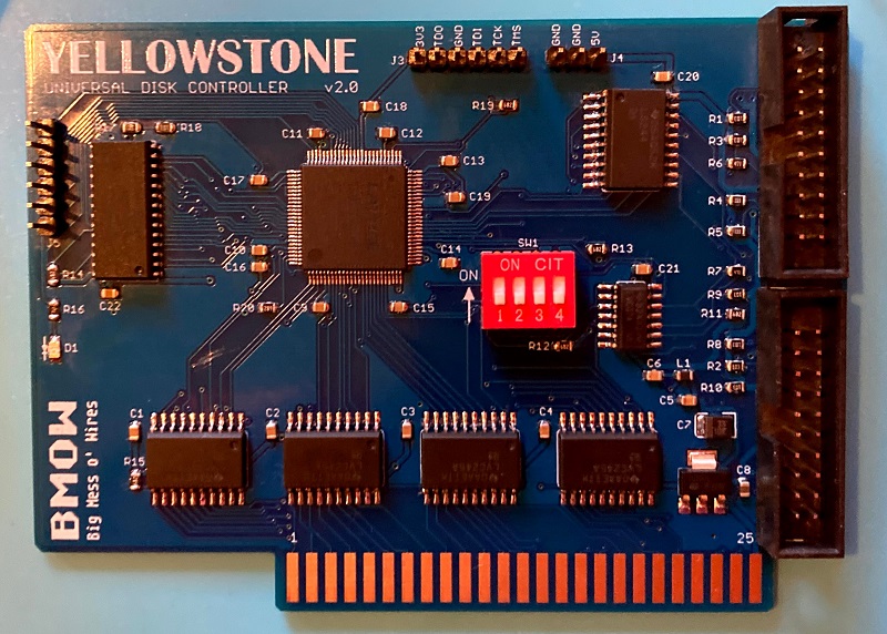
I’ve finished assembling the first prototype board of Yellowstone 2.0, my FPGA-based universal disk controller for Apple II computers. I used a syringe to dispense solder paste onto the pads, and baked the board on a hot plate with the surface mount components, before manually soldering all the through-hole components. It took about 1.5 hours to assemble, so it’s not something I’d want to do by hand very often. But for a one-off prototype it’s OK.
The board doesn’t work. After lots of puzzling and scratching my head, I determined that the data bus signal D5 is always stuck at 1. After another hour or two of puzzling, I discovered why. What’s wrong with this picture?
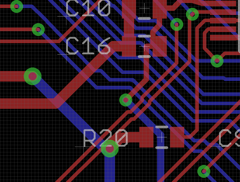
The image shows the traces and components on a small section of the Yellowstone 2.0 board. There’s a signal trace going directly through an unrelated power supply via under the R20 text. That signal trace is D5, so D5 is directly connected to the 3.3 volt supply. Arghh! How did I make that mistake? Why didn’t the layout software’s design rule checker warn me about the overlapping trace? When I rerun the DRC, it does warn me, so it’s not the software’s fault. I must have moved that trace just before I finalized the board layout, and forgotten to rerun the DRC. That’s an expensive mistake.
I can move the overlapping signal trace out of the way and get some new PCBs made, but that will take a few weeks. Meanwhile, can I fix this board somehow, so I can continue testing it? Usually I can fix mistakes like these by cutting a signal track with a razor, and soldering narrow gauge wire to replace the severed track. But here there’s not much room to work with for cutting. For most of its length, the problematic signal trace is only a few mils away from another signal trace, and my hand-cutting skills aren’t that precise. I also need to cut the track twice: once above the via overlap, and a second time below it, and then join them with wire. I think I can probably do it, but it’ll be tricky.
Read 7 comments and join the conversation7 Comments so far
Leave a reply. For customer support issues, please use the Customer Support link instead of writing comments.
Oh no, that’s heartbreaking! Good luck with the bodge and future testing.
Instead of cutting right near the mistake cut it at the ends, Upper right corner has more room, if you are lucky other end will also have a spot with more space to work with. Finally some people insist on soldering to the cut trace, but you can just solder to pads/vias, much easier.
Doesn’t look too bad to me… place your cutter between the tracks and cut outwards. Even in the worst case, you’ll just have to add another wire for the unrelated track if you do indeed cut it.
Alternatively, just cut the 3.3 V track at the bottom, fix that and solder R20 in a way that doesn’t use its left pad.
Dude. Good luck on the patch. This has to be a real punch in the gut.
I’ve successfully patched the dodgy signal trace, but the board still doesn’t work. It crashes somewhere in the card’s boot-up ROM. It’s difficult to tell exactly what’s going on, and I’m not sure if it’s software or hardware. I’ll keep looking.
If you can’t cut just the single trace, cut both of them and put in a jumper for both.
After patching the buggy signal trace, there’s some analog-level problem that I’ve been unable to troubleshoot or fix. Signal glitching, maybe. It’s possible that some of the chips were damaged when that signal trace was directly connected to 3.3 volts and I tried to use the board, and the trouble I’m seeing now could be related to that. I’m trying to decide whether I should continue troubleshooting or if I should assemble another board with new parts to rule out chip damage. I guess assembling another board would be the smartest path, but I’m not excited about doing that.