Archive for April, 2020
Building a 12V DC MagSafe Charger
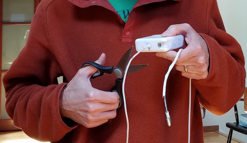
Now that I have a solar-powered 12V battery, how can I charge my laptop from it? An inverter would seem absurdly inefficient, converting from 12V DC to 110V AC just so I can connect my Apple charger and convert back to DC. It would work, but surely there’s some way to skip the cumbersome inverter and charge a MacBook Pro directly from DC?
Newer Macs feature USB Type C power delivery, a common standard with readily available 12V DC chargers designed for automotive use. But my mid-2014 MBP uses Apple’s proprietary MagSafe 2 charging connector. In their infinite wisdom, Apple has never built a 12V DC automotive MagSafe 2 charger – only AC wall chargers. There are some questionable-looking 3rd-party solutions available, but I’d rather build my own.
Step 1: Cut the cord off a MagSafe 2 AC wall charger. Yes that’s right. Being a proprietary connector, there’s no other source for the MagSafe 2. Fortunately I already had an old charger with a cracked and frayed cable that I could use as a donor. Snip!
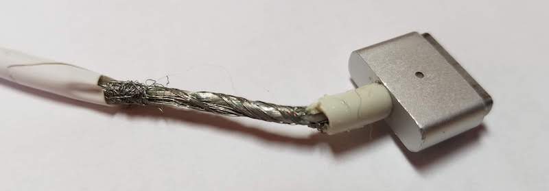
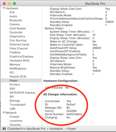
The choice of AC wall charger matters more than you might expect. Inside the MagSafe 2 connector is a tiny chip that identifies the charger type and its maximum output power. The Mac’s internal charging circuitry won’t exceed this charging power, no matter what the capabilities of the power supply at the other end of the cable. Pretty sneaky, Apple! Official MagSafe 2 chargers come in three varieties of 45W, 65W, and 85W. My donor MagSafe 2 has the 85W id chip inside, so I can charge at the fastest possible rate.
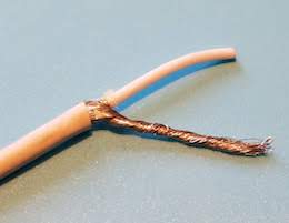
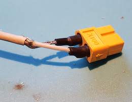
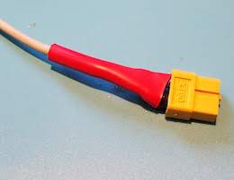
After cutting the charger cable, inside I found another insulated wire which I assumed to be the positive supply, surrounded by a shroud of fine bare wires which I assumed to be the ground connection. I’m not sure why Apple designed the cable this way, instead of with two separate insulated wires for power and ground. The braid of fine bare wires was awkward to work with, but I eventually managed to separate it and twist it into something like a normal wire. I soldered the power and ground wires to an XT60 connector and covered them with electrical tape and heat shrink. I also repaired the cracked and frayed cable sections.
Step 2: Get a DC-to-DC boost regulator. The input should be 12V, with a few volts of margin above and below. But what about the output? What’s the voltage of a MagSafe 2 charger? My donor charger says 4.25A 20V, but I couldn’t find any 12V-to-20V fixed voltage boost regulators. Happily I think anything roughly in the 15-20V range will work. For comparison, I have a 45W Apple charger that outputs 14.85V and a 3rd-party MagSafe 2 charger that outputs 16.5V. I chose this 12V-to-19V boost regulator with a maximum output power of 114W. At 85W, I’ll be pushing it to about 75% of maximum.
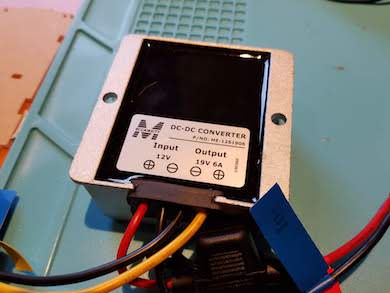
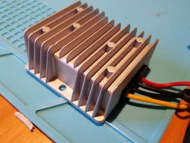
Step 3: The moment of truth. Would my expensive computer burst into flames when I connected this jury-rigged DC MagSafe charger? I held my breath, plugged in the cable, and… success! Of course it worked. The orange/green indicator LED on the MagSafe 2 connector worked too.
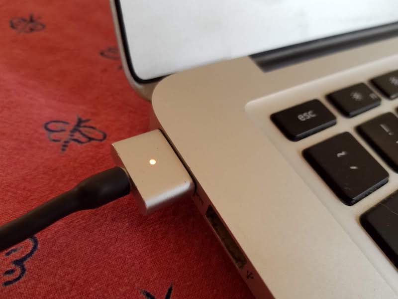
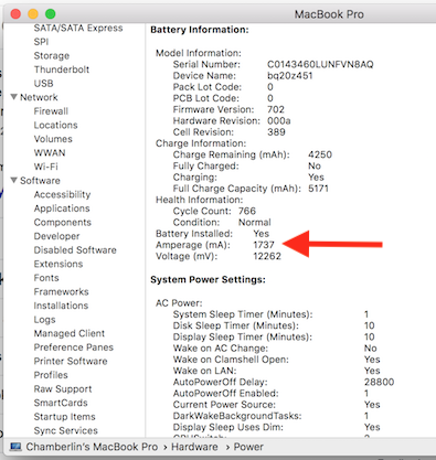
Opening the Mac’s System Information utility and viewing the Power tab, I could see that my charger was correctly recognized and working. The “Amperage” status also showed the battery was charging at a rate of 1737 mA (positive numbers here indicate charging, and negative numbers discharging). This seemed low – with the battery at 12.2V, that implied it was charging at roughly 21W instead of 85W. But when I connected an AC wall charger in place of my DC charger, the charging rate was almost identical. Because my battery was almost 100% charged, I think the charging rate was intentionally reduced. I’ll check again later when my battery is closer to 0%.
Goodbye, inverter. With just a few hours of work, I had a functioning 12V DC MagSafe 2 charger. Time to sit back, enjoy a beer, and celebrate victory.
Checking the Numbers
I like numbers. Do you like numbers? Here are some numbers.
This charging method is about 95% efficient, according to the claimed efficiency rating of the boost regulator. I can also leave the regulator permanently connected, since its no-load current is less than 20 mA. In comparison, charging with an inverter and an AC wall charger is about 77% efficient (85% for the inverter times 90% for the wall charger). And an inverter probably can’t be left permanently connected, since it has a constant draw of several watts even when no appliances are plugged in.
My “12V battery” is actually a Suaoki portable power station with a 150 Wh battery capacity. How many times can I recharge my MacBook Pro from this? Checking the Mac’s System Information data, I infer it has a 3S lithium battery with an 11.1V nominal voltage. System Information says the battery’s fully-charged capacity is 5182 mAh (which means my battery is old and tired), so that’s 57.5 Wh. A bit of web searching reveals that a fresh battery should have a capacity of 71.8 Wh. That means I should be able to recharge my MBP from 0% up to 100% twice, before exhausting the Suaoki’s 150 Wh battery.
Is the charging current over-taxing the Suaoki? How much current am I actually drawing from it? 85W of output power with 95% efficiency implies about 89.5W of input power to the boost regulator. At 12V that would be roughly 7.5A drawn from the Suaoki battery. But the Suaoki’s lithium battery falls to about 9V before it’s dead, and at 9V it would take 10A to reach the same number of watts. The Suaoki’s 12V outputs are rated “12V/10A, Max 15A in total”, so in the worst case I’d be running right up to the maximum.
What happens if I charge my MacBook and charge a couple of phones from the Suaoki’s USB ports at the same time? Would this be too much? I wouldn’t be exceeding the maximum rating of the USB ports, and (probably) wouldn’t be exceeding the maximum rating of the 12V ports, but the combination might be too much. At 85W for the MacBook, and maybe 10-20W each for two phones, the worst-case total could be as much as 125W. The Suaoki manual says “the rated input power of your devices should be no more than 100W”, but I think this refers to the AC inverter, not the system as a whole. Powering 125 watts from a 150 Wh battery is a discharge rate under 1C, which seems quite reasonable for a lithium battery. It’s probably OK. Now, back to charging!
Read 32 comments and join the conversationNew Features for ADB-USB Wombat
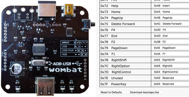
New firmware 0.3.5 is now available for the ADB-USB Wombat! The Wombat is a bidirectional ADB-to-USB and USB-to-ADB converter for keyboards and mice. Connect modern USB keyboards and mice to a classic ADB-based Macintosh, Apple IIgs, or NeXT, or connect legacy ADB input hardware to a USB-based computer running Windows, OSX, or Linux.
Firmware version 0.3.5 adds some new items to the feature list:
- Support for remapping the Power Key for ADB-to-USB mode. This was a frequently requested feature from people using an old Apple Extended Keyboard with a modern PC or Mac. The default is unmapped, but you can use the Custom Keymap Tool to map it to a function key or anything else.
- Separate keycodes for left and right side Shift, Control, and Option keys. Now if you wish, you can configure the left modifier keys to have different behavior than the right modifiers. I’d thought this was already happening before, but some extra keyboard magic was needed to make it work. The Apple Extended Keyboard II supports separate left/right side modifiers, but the AEK I doesn’t. If you’ve got an Appledesign keyboard or other model, let me know how it behaves.
- Option to disable mouse-wheel arrow keys. When using a USB mouse on an ADB computer, there’s no equivalent of the mouse wheel. The Wombat converts mouse wheel rotations into keypresses of the up/down arrow key, which accomplishes a similar result in most software. If it causes problems, this arrow keys behavior can now be disabled using the Custom Keymap Tool.
You’ll find firmware 0.3.5 in the Downloads section of the Wombat page. And if you don’t have a Wombat yet, they are available and shipping now.
Read 2 comments and join the conversationResidential Solar Power and the Duck Curve
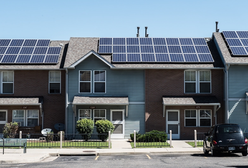
Sometimes you can have too much of a good thing. Take a look at the growth of residential roof-top solar power in California. For individual customers who are blessed with sunny weather, installing solar panels can be a smart financial decision and a great way to escape the region’s high electricity prices. But for the utility companies and for the region as a whole, the results may not be what you’d expect. On sunny California afternoons, the state’s wholesale electric prices can actually turn negative. There’s a glut of electric generation, supply exceeds demand, but all that electricity has to go somewhere. So factories are literally paid to use electricity.
Negative Electricity Prices
What is going on here? It’s important to understand that all electric usage must be matched with electric generation occurring at the same moment. Aside from a few small-scale systems, there’s no energy storage capability on the grid. If customers are using 5 gigawatts, then there needs to be 5 gigawatts of total generation from power plants at that same time. If there’s not enough generation, you get brownouts. And if there’s too much generation, you either get over-voltage or over-frequency, damaged equipment, fires, and other badness.
Maintaining this balance is difficult. Electric demand is constantly changing, but it’s not so easy to switch a gas-fired power plant on and off. There’s some ability to adjust output, but it’s not perfect. For most residential solar installations, the utility company is obligated to buy any excess electric generation, whether they need it or not. There’s no way for the utility company to tell you “thanks but we already have enough power right now, please disconnect your solar panels”. So what happens when there’s too much electricity? You pay somebody to take it.
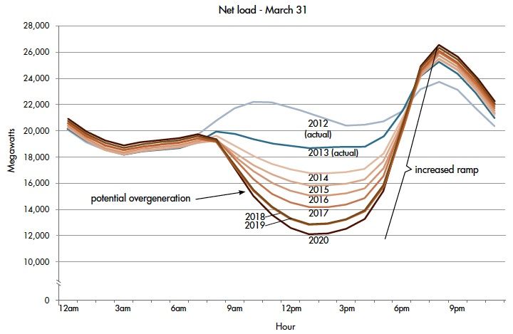
The challenge is illustrated by something called the duck curve, so-named because the graph supposedly looks like a duck. This curve shows the hour-by-hour net electricity demand for California, after excluding solar power. As the day starts, net demand is about 19 GW. Then around 8:00 AM, the sun rises high enough above horizon obstructions and solar power begins to flood the grid. Net demand from gas and coal power plants drops hard. Then around 6:00 PM the trend reverses. As the sun is setting, solar power generation declines to zero while everyone switches on lights and air conditioning. Net demand skyrockets, creating a huge demand wall peaking about 26 GW at 8:00 PM. It’s enough to make any grid operator swoon.
Every year, this problem gets worse as more and more residential customers install solar panels. This trouble is likely to grow even faster now due to California’s new first-of-its-kind solar mandate. As of January 1st 2020, the state requires that all newly-constructed homes have a solar photovoltaic system. Expect the duck curve to quack even more than before.
It’s not hard to understand why grid operators view residential solar as a mixed blessing. During the day it provides cheap clean electricity, and that’s a good thing. Gas and coal plants can be idled, saving fuel and reducing emissions. But solar power can’t eliminate those gas and coal plants entirely – they’re still critically important for evenings and night. So during the day many of those plants are just sitting there doing nothing. The power plants still need to be built, and staffed, and maintained, even if they’re only in use half the time.
Grid-Scale Energy Storage
Given the daytime production of solar power, there’s no amount of solar that could ever replace 100% of the state’s energy needs. By itself, it will never enable us to get rid of all those gas and coal power plants. That’s a big problem – a huge problem if you care about the long term and the environment. If you’re a young engineer casting about for a field in which to make your career, I believe you could do very well dedicating your career to solving this challenge.
The answer of course is energy storage. What’s needed is a way to take the dozens of GWh of solar power generated between 8:00 AM and 6:00 PM, and spread it out evenly across a 24 hour period. But how?
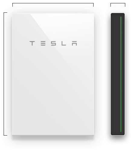
You might be thinking of solutions like the Tesla Powerwall, or similar home-based battery storage systems. The Powerwall 2 is a very cool device that can store 13.5 kWh. You can use it to store excess power generated by your solar panels during the day, and drain it at night to run your lights and appliances, helping to smooth out the duck curve.
But the Powerwall is too small and too expensive to really make economic sense. 13.5 kWh is not enough to get a typical home through the night, and the hardware costs about $13000 installed with a 10-year lifetime. You’d need to achieve massive cost savings for the Powerwall to pay for itself during those 10 years. It’s good for the utilities, and if every residential solar customer had a Powerwall, it would go a long way towards smoothing the duck curve and eliminating many of those gas and coal power plants. But it’s probably not a good value for you, the individual residential customer.
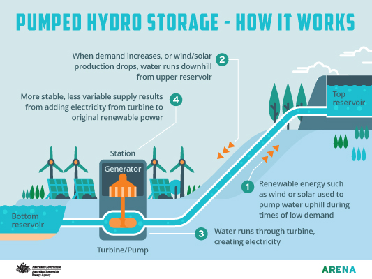
Image from arena.gov.au
Looking at the whole system, what’s really needed is grid-scale energy storage. Instead of individual customers storing a few tens of kWh with batteries, we need industrial-scale systems storing many MWh or GWh by pumping millions of gallons of water uphill or with other storage techniques. These are big engineering projects, and some effort has already been made in this direction, but it’s still early days. Aside from massive battery arrays and pumping water uphill, other options include heating water and storing compressed air underground. Nothing works very well yet, but watch this space. The world needs this.
TLDR: It matters not only how much clean energy can be generated, but when it’s generated. The variable output of solar power is a big problem that prevents eliminating more gas and coal power plants. A large scale energy storage solution that’s cheap and efficient would be a tremendous win.
Read 7 comments and join the conversation

