Archive for May, 2019
Alternative AVR Programming Header Ideas
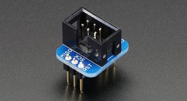
That ubiquitous six pin header for in-circuit programming of Atmel AVR microcontrollers – it’s the standard, but it’s not a great standard where size and cost are a concern. Can I do better?
Programming most AVRs requires a six wire interface, with a clock, serial in, serial out, reset, power, and ground. It’s common to include a 3 x 2 pin 0.1 inch header on any AVR-based board. Typically a keyed box header is used to prevent accidental backwards cable attachment, like the header on the Adarfruit breakout board shown above, but sometimes bare 3 x 2 pin 0.1 inch headers are used.
That’s fine for hobbyist work or building a prototype, but when building larger numbers of AVR-based boards, the 3 x 2 pin 0.1 inch header has two significant drawbacks. The first is the component cost and related assembly cost for a header that will only ever be used once, for a few seconds during manufacturing. It’s not a huge cost, but it’s still a factor when trying to minimize the cost per unit – why throw away money? The second drawback is the relatively large physical size of the 3 x 2 pin 0.1 inch connector. For small boards containing mostly surface mounted parts, the ICSP header can complicate layout and routing, or require enlarging the PCB.
Ideally we want a programming connector with these attributes:
- zero per-unit cost
- small footprint, preferably one-sided
- keyed to prevent backwards cable connections
- holds cable firmly attached to the board
Here are some options to consider.
Empty Footprint 0.1 inch
The simplest option is keep the standard 3 x 2 pin 0.1 inch header footprint, but don’t actually solder a header into it. When it’s time to do programming, place a 3 x 2 header in the holes, and apply some sideways finger pressure to ensure the pins make solid contact with the hole plating. It’s low tech, but it works.
A small optimization is to use a 3 x 2 pin 0.1 inch lock header footprint, where the holes for the individual pins are very slightly offset instead of appearing in a perfect grid. This helps hold the header in place temporarily with friction, so finger pressure normally isn’t needed. It’s what I do for Floppy Emu programming, as shown here:
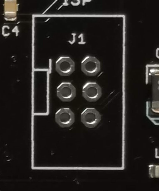
This approach eliminates the cost of an otherwise-useless programming header, but it’s still too big and doesn’t prevent backwards insertion. And even with the lock header footprint, it’s not great at holding the cable in place for extended periods of development or debugging. The pins often slide out of the holes.
Empty Footprint 0.05 inch
A second option is to use an empty 0.05 inch header footprint, which reduces the required board area to just 25% of original. That’s great, and this might be a good solution. But most AVR programmers have a 0.1 inch cable, so a 0.1 inch to 0.05 inch adapter will need to be built or purchased. That’s a minor drawback, but it only needs to be done once.
0.05 inch pin headers are fairly delicate. Would they hold up to hundreds of insertions and removals, with the added forces of finger pressure or lock headers?
This solution is also not keyed to prevent backwards cable insertion, nor does it grip the cable tightly.
Empty Non-Rectangular Footprint 0.05 inch
If I’m contemplating building a 0.1 inch to 0.05 inch adapter anyway, there’s no reason the 0.05 inch end needs to retain the standard 3 x 2 layout. I could do something with 4 pins in one row and 2 pins in a second row, or any other kind of irregular pin spacing that would prevent backwards cable insertion. Maybe a 7 pin single row design, with one of the pins removed. This would make the footprint area slightly larger than a 3 x 2 layout, but it might be worth it to prevent accidental backwards connections.
Pogo Pins
Any kind of footprint with plated-through holes will hinder routing and component placement on both sides of the board. Spring-loaded pogo pins provide an alternative approach, making it possible to build a one-sided programming interface with exposed pads, similar to this:
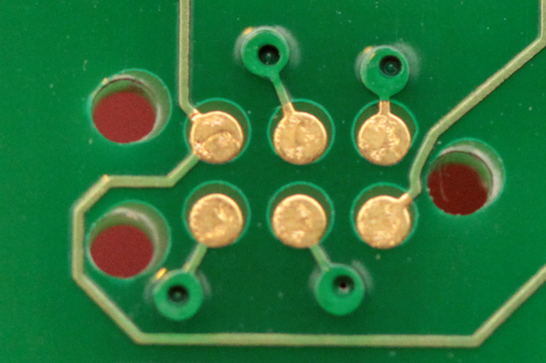
With 0.05 inch spaced pogo pins this allows for the smallest footprint of all, but the pogo pins need to be held against the board with one hand during programming, making it awkward to use. It’s OK for a programming operation lasting a few seconds, but not for anything longer.
This simple AVR ICSP pogo pin adapter from Tindie shows one such approach:

It’s nice, but there’s nothing to help align the cable or prevent backwards connections.
For a fancier solution, there are pogo pin cables from Tag-Connect that include alignment pins and optional locking legs to hold the cable firmly on the board:
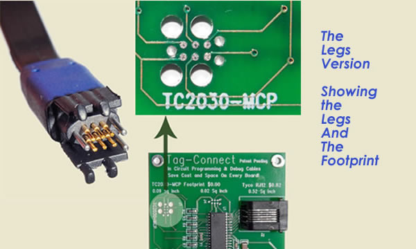
But when you include the area needed for the alignment pin holes, the Tag-Connect footprint is essentially the same area as the standard 3 x 2 pin 0.1 inch header footprint, and the size advantage is lost. And with the version of the Tag-Connect cable that has locking legs, the required footprint area is even larger. Look at this beast:

Conclusion
So what’s the best option? I don’t think any of them is a clear winner – they all have advantages and disadvantages. I really like the idea of pogo pins and exposed PCB pads, but the required alignment pin holes mostly negate the space savings, and I don’t like the idea of always needing one hand to hold the cable in place. For my purposes, I think the non-rectangular footprint with 0.05 inch headers is worth exploring further. I’ll see what I can cobble together for testing.
Read 12 comments and join the conversationDaisy Chainer Testing
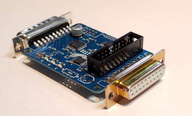
Good news: the Daisy Chainer for Floppy Emu is finished, and working nicely in all my tests. With the Daisy Chainer, a mix of real and emulated disk drives can be combined into a single Apple II daisy chain for maximum flexibility. The real drives can be attached before or after the Floppy Emu.
I have a few Daisy Chainer boards available for sale now. Send me an email if you’re interested in getting one (use the Contact link at the page’s upper-right).
Not-so-good news: newly-assembled Daisy Chainer boards are a pain to test, and this is something I didn’t account for. A true functional test requires connecting the board to a Floppy Emu, an Apple II, and a variety of other disk drives, and then running through many different permutations of daisy chain configuration and disk emulation modes. It requires 15 minutes or more. That’s OK for a few hand-assembled units, but there’s no way I can do that for a larger production run.
To support faster testing, I’ve designed two special test boards that plug into the male and female DB19 connectors on the Daisy Chainer. These will enable some automated loopback testing of the main board using its own microcontroller. It won’t be a perfect test, but combined with some other automated tests for things like pin-to-pin solder shorts it should detect most likely assembly defects.
The problem is that in order to support the automated testing with the special test boards, I need to make some modifications to the Daisy Chainer PCB. I’ve finished that work, but I’m waiting for PCB delivery and then I need to assemble a second prototype. So it will probably be at least a month until full production of more Daisy Chainers is possible.
This is the first time I’ve ever been forced to redesign a PCB not because there was a problem with the device itself, but simply because the device was difficult to test efficiently. Lesson learned: when designing anything that you expect to build more than 10 units of, planning for testing should be an integral part of the design process.
Read 2 comments and join the conversationFloppy Emu Firmware Update: Smartport Unit 2 Mode
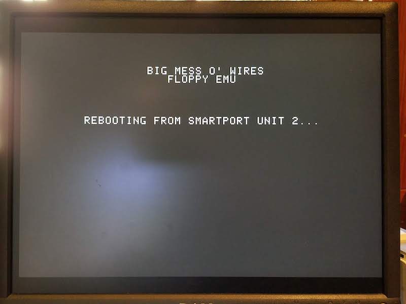
Celebrate Friday with a firmware update for the Floppy Emu disk emulator! This firmware adds a handy new disk emulation mode for Apple IIGS computers called Smartport Unit 2 mode. It’s what I called “chameleon mode” in an earlier post, and it’s very helpful for one specific configuration: you’re using the Floppy Emu as a Smartport hard disk, and the Emu is “unit 2” daisy-chained behind an Apple 3.5 inch floppy drive. With the new firmware, it’s now possible to boot from Smartport unit 2!
Normally an Apple IIgs in this configuration could only boot from the Apple 3.5 inch floppy drive (the 1st drive unit in slot 5), limiting the configuration’s usefuleness. Smartport Unit 2 mode causes the Floppy Emu to initially appear as a 5.25 inch drive in slot 6, which the IIgs will boot from, and load a small bootstrap program. This program will modify the Smartport unit priority table in RAM to give Unit 2 priority over Unit 1, and then reboot from slot 5. Presto, unit 2 boots.
You should only use Smartport Unit 2 mode when the Floppy Emu is daisy-chained behind an Apple 3.5 inch floppy drive. In all other cases, continue to use regular Smartport mode.
Get the firmware here: apple-II-0.2H-F25-modelBC
Note this firmware also contains some changes needed to support the forthcoming Daisy Chain Adapter. There shouldn’t be any visible differences, but be on the lookout for possible problems with daisy chaining, so you can revert to the previous firmware version if needed.
Read 6 comments and join the conversation
