Archive for February, 2019
Part Selection and Schmitt Trigger Oscillator

I often obsess over little details of my circuit designs, and the daisy-chain adapter for Floppy Emu is no exception. The design needs a small CPLD for the daisy-chaining logic, and for various reasons I have narrowed the choices to the Lattice ispMACH LC4032ZE and LC4032V. These are both 32 macrocell CPLDs, and are very similar except for a few details:
LC4032ZE – 48 pins, 0.5 mm pin pitch, 1.8V core, built-in oscillator
LC4032V – 44 pins, 0.8 mm pin pitch, 3.3V core
The 4032ZE is the newer of the two options, and the 4032ZE supply at distributors is a bit more plentiful. It also has a built-in 5 MHz RC oscillator with +/- 30% accuracy, which can be divided down to the kHz range or lower frequencies without using any macrocells. As it happens, the daisy chain adapter needs a clock source in the kHz range for periodic tasks, but the exact frequency isn’t too important, so this is perfect.
The drawbacks of the 4032ZE are its core voltage and its pin pitch. With a 1.8V core serving 3.3V I/O to and from 5V disk drives, I’d need to design a three-voltage system. In practice that means an additional voltage regulator, some extra decoupling capacitors, and a bit more headache with the board layout. 0.5 mm pin pitch means the pins are very tightly spaced. It creates a greater likelihood of soldering errors and hard-to-see solder shorts during assembly. Basically it will make assembly and testing of boards more challenging.
The 4032V looks like a good alternative, with a 3.3V core and a much wider pin pitch. But it lacks any built-in oscillator. If I want a clock source, even an inaccurate one, I’ll have to provide one externally. That will add a bit to the board cost and complexity. The 4032V itself is also slightly more expensive than its twin. In the end, it’s not obvious to me whether the 4032V or 4032ZE is the better choice overall.
Which one would you choose?
Schmitt Trigger Oscillator
If I choose the 4032V, then I’ll be looking for a simple and inexpensive way to provide an external clock signal to it. Something around 10 kHz would be preferred. I can probably tolerate inaccuracies in the frequency of 50% or more, over time on the same board or between different boards.
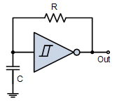
I could use a single chip oscillator like a MEMS oscillator, but I’m drawn instead to the idea of a Schmitt Trigger RC oscillator. It’s cheaper, and it also has a nice old-school vibe. The circuit is simply a single inverter with its output fed back to its input through a resistor, and with its input also connected through a capacitor to ground.

The frequency of the Schmitt Trigger RC oscillator depends on the values of the capacitor and resistor, the hysteresis of the inverter, and the supply voltage. Calculators exist to help predict the frequency, but in practice I’d probably need to tune it experimentally.
I’m fine with some variation in the frequency, as long as it doesn’t vary wildly. A variance of 2x or more could become problematic. Given the tolerance of the capacitor and resistor values, temperature-dependent capacitance changes, process variations between inverters, and possible supply voltage fluctuations, what range of frequency variation is a Schmitt Trigger RC oscillator likely to experience?
Would I be better off paying more for a standard oscillator, even though I don’t need the high accuracy? Or would I be better off using the 4032ZE with its built-in oscillator, and not stressing about the core voltage and pin pitch?
Read 7 comments and join the conversationDaisy Chain Daydreams

Some Apple II computers can daisy-chain disk drives: connect multiple disks, one after another in a single chain. I’m exploring options for the BMOW Floppy Emu disk emulator to support daisy-chaining more flexibly than it does now. I’d love your thoughts on whether you’d find this personally useful – please read below and leave a note in the comments section.
Daisy Chain Basics
Daisy-chaining makes it possible to connect many different disk drives to the same computer, without needing a separate disk controller card for each drive. Among early Apple computers, only the Apple II family has daisy-chaining capability – the Macintosh and Lisa don’t support it. Even among Apple IIs, daisy-chaining is only very useful on the Apple IIgs, the rare Apple IIc+, and to a lesser extent the Apple IIc. Other Apple II models lack the necessary hardware or the ability to control multiple types of drives, so this discussion will focus on the IIgs.
The Apple IIgs supports three different types of disk drives:
- “dumb” 3.5 inch drives, like the Apple 3.5 Drive (A9M0106)
- “smart” drives, like Floppy Emu’s Smartport HD mode, or the Apple Unidisk 3.5 (A2M2053)
- 5.25 inch drives
At most two drives of each type can be placed in the chain, six drives in total.
Drive Ordering and Boot Limitations
A critical requirement is the ordering of drives in the daisy chain: the dumb 3.5 inch drives must appear before the smart drives, which must appear before the 5.25 inch drives. This requirement stems from the way the disk port’s control signals are multi-purposed to serve several different types of drives, where some types didn’t yet exist when the older types were designed. You can try physically connecting the drives in a different order, but some of them won’t work and may even be damaged.
The ordering requirements have the side-effect of constraining the computer’s options for boot disks. With complex daisy chains, these constraints can become inconvenient and annoying.
Dumb 3.5 inch drives and smart drives are placed in a single logical group that’s mapped to slot 5. Only the first drive in that group can be used as a slot 5 boot drive. If two dumb 3.5 inch drives are connected, only the first can be used to boot the computer. And if both a dumb 3.5 inch drive and a smart drive are connected, only the 3.5 inch drive can be used to boot the computer. The smart drive can never serve as a boot drive, in this case.
With the Floppy Emu
The Floppy Emu was originally designed as a Macintosh device, and it lacks a daisy chain output connector. That means it can work happily in an Apple II daisy chain with other drives, but only as the last drive in the chain. Often this isn’t an issue, but for some combinations of emulation modes and disk drives, it causes difficulties. Here are some Apple IIgs setups that aren’t currently supported, due to Floppy Emu’s absence of a daisy chain output:
- Floppy Emu in Smartport HD emulation mode, combined with one or two 5.25 inch drives.
- Floppy Emu in 3.5 inch emulation mode, combined with one or two 5.25 inch drives.
- Floppy Emu in 3.5 inch emulation mode, combined with another 3.5 inch drive, where Floppy Emu serves at the first (boot) drive.
- Floppy Emu in 5.25 inch emulation mode, combined with another 5.25 inch drive, where Floppy Emu serves at the first (boot) drive.
Giving a daisy chain output to the Floppy Emu would enable all of the above setups. Unfortunately it would also add more complexity to the device, because the daisy chain output isn’t simply another physical connector with its data signals bussed from the daisy chain in. It’s a complex logic device whose behavior must change depending on what type of drive is being emulated, whether that drive is currently enabled by the computer, and what type of drive (if any) appears next in the daisy chain. Depending on the circumstances it must alternately cross-over, gate, or otherwise modify the disk control signals. This would require a new programmable logic device, likely a small CPLD similar to the one Floppy Emu uses for disk emulation. But the added cost and complexity would be little benefit to anyone except Apple IIgs owners.
I’ve been exploring a different route – a stand-alone daisy chain adapter rather than a modification to the Floppy Emu. This adapter would function like a T splitter, taking Floppy Emu’s place in the daisy chain, with a connection for the Floppy Emu as well as a standard daisy chain output for additional drives. This would provide a daisy chaining option for Floppy Emu owners who want one, without negatively impacting anything else.
Note there’s still one Apple IIgs setup that can’t be supported: Floppy Emu in Smartport HD emulation mode, combined with another 3.5 inch drive, where Floppy Emu serves as the boot drive. The Apple II drive ordering and boot requirements make this combination impossible, as described earlier (except for some very awkward work-arounds). This has nothing to do with the Floppy Emu or its lack of a daisy chain output – the same limitation exists with other 3.5 inch and smart drives.
My question to you, Apple II reader, is whether a stand-alone daisy chain adapter would interest you for enabling the Apple IIgs daisy chain setups listed above. It would be clearly a niche item for a niche product, so I’m unsure if it makes sense.
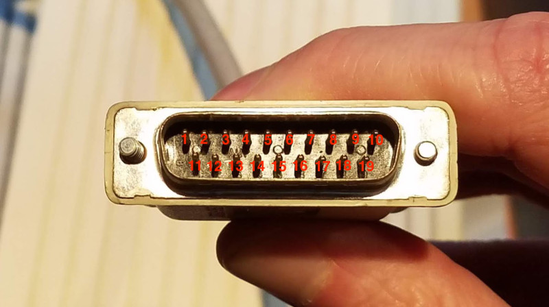
Aside from the cost of manufacturing and possible low demand for this adapter, the biggest hurdle would be finding a supply of female DB-19 connectors for the daisy chain output. This could be a major challenge. When the global supply of male DB-19 connectors was exhausted a few years ago, I had to commission the manufacturing of 10,000 new ones to continue with Floppy Emu production. That was very expensive, and I definitely can’t afford to do something like that here. Hopefully enough DB-19F’s are still in a surplus parts warehouse somewhere!
Read 16 comments and join the conversationThe End of the ROM-inator

All good things must come to an end, and today it’s the end of the Macintosh ROM-inator II SIMM and SIMM programmer. The DIY ROM-inator I kit was discontinued a year ago, and now the ROM-inator II is also being retired. I hate to see it go, but as I’d cautioned more than year ago, this was inevitable.
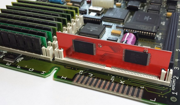
The ROM-inator II SIMMs (both standard and MEGA sizes) use a set of 16 megabit 5 volt flash memory chips to interface directly with the Macintosh bus. There was only one manufacturer still making this chip, and they moved it to “end of life” status in March 2018. Supplies dwindled, prices went up, and now they’re all gone. The 64-pin SIMM socket needed for the SIMM programmer became similarly hard to get, with only one known remaining supplier with a finite number of new-old-stock parts.
Both technical challenges might be solvable, with enough effort. Perhaps level converters with 3.3 volt flash memory could be integrated on the SIMM. The top edge of the SIMM might be redesigned with a different edge connector to fit a programmer socket that’s still commercially available. But candidly, the ROM-inator was always a somewhat poor value proposition for me, requiring more effort to maintain and support than was reasonable given its sales. I’m not interested in a big new engineering effort to redesign the hardware now.
There are also some issues on the software side that would need attention, if the ROM-inator II were to continue. There’s an unknown bug involving the SIMM programmer’s bootloader, which often causes the programmer to fail to be detected by the software. On MacOS Sierra and later, the software requires an awkward series of quitting and restarting before it will successfully connect. The driver and software application also need to be digitally signed, to shut up the warnings from the latest versions of Windows 10 and MacOS.
Smaller capacity 5V flash memory chips remain available, and I could conceivably design a “ROM-inator II Mini” with 512KB or 1MB of total storage. That would be enough for a modified system ROM with the new startup sound, new icons, HD20 support, and 32-bit clean ROM. But it would leave no space available for a ROM disk, and no way for users to reprogram the SIMM. And there’s already somebody on eBay who’s selling almost exactly that.
Thanks, ROM-inator. It’s been a fun ride!
Read 11 comments and join the conversation

