Archive for June, 2018
Cortex M4 Interrupt Speed Test

How quickly can a microcontroller detect and respond to changing inputs? Fast enough to replace a dedicated combinatorial logic chip, like a mux? I finally have some test results to begin answering this question.
My goal here is a potential redesign of the Floppy Emu disk emulator. The current design uses a microcontroller for the high-level logic, and a CPLD for the timing-critical stuff. But if a new microcontroller were fast enough to handle the high-level logic and the timing-critical stuff, I could simplify the design and eliminate the CPLD.
This is the fourth post in a series:
1. Thoughts on Floppy Emu Redesign
2. Thoughts on Low Latency Interrupt Handling
3. More on Fast Interrupt Handling with Cortex M4
Background
Let’s consider a mux-like function performed by Floppy Emu’s CPLD, as part of some disk emulation modes. It behaves like a 16-to-1 mux: 16 data inputs, 4 address inputs, and 1 data output. In order to properly emulate a disk drive, the mux must respond to changing address or data inputs within 500 nanoseconds. For my tests, I used an ARM Cortex M4 running at 120 MHz: specifically the Atmel SAMD51 on an Adafruit Metro M4 Express board.
At 120 MHz, 500 nanoseconds is 60 clock cycles: that’s how much time is available between an input’s rising/falling edge and the updated data output. The previous posts in this series examined the datasheets and performed some static code analysis, attempting to decide whether this was realistically possible in 60 clock cycles. The answer was “maybe”, awaiting some real-world timing experiments.
Timing It
Here’s a very simple interrupt handler. It doesn’t even attempt to perform the 16-to-1 mux function yet. It sets an output pin high when the handler begins running, and low when it finishes running, so I can monitor the timing with a logic analyzer. The body of the interrupt handler clears the interrupt flags for external interrupts 1, 2, 3, and 6 (where I connected the address inputs). This establishes a lower bound on how fast the real interrupt handler could possibly be, once I’ve added the 16-to-1 mux functionality and many other related pieces of logic.
void EIC_1236_Handler(void)
{
	PORT->Group[GPIO_PORTA].OUTSET.reg = 1 << 2; // PA2 on

	uint32_t flagsSet = EIC->INTFLAG.reg; // which EIC interrupt flags are set?
	flagsSet &= 0x4E;  // we only act on EIC 6, 3, 2, and 1
	EIC->INTFLAG.reg = flagsSet; // writing a 1 bit clears the interrupt flags.

	// now do something, based on which flags were set. More flags may get set in the meantime...

	PORT->Group[GPIO_PORTA].OUTCLR.reg = 1 << 2; // PA2 off
}
Here are the results from the logic analyzer. The inputs PH2, PH1, PH0, and SEL are from a Macintosh Plus querying to test whether a disk drive is present. ISR is the timing output signal from my interrupt handler.

Every time there's an edge on one of the input signals, there's a brief spike on ISR. Looks good. Let's zoom in:

For the highlighted input edge, the delay between a rising edge of PH1 and the start of the interrupt handler is 175 nanoseconds (0.175 µs). Other edges are similar, but not identical. For this sample, the delays ranged between 175 and 250 ns. The width of the ISR pulse (the duration of the interrupt handler) was either 50 or 75 ns. So the total time needed to detect an input edge and run a minimal interrupt handler function is about 225 to 325 ns. That only leaves a few hundred nanoseconds to do the actual work of the interrupt handler, which doesn't seem promising. (The precision of the timing measurements was 25 ns.)
Test conditions:
- NVRAM line cache was enabled
- NVRAM wait states set to "auto"
- L1 instruction/data cache was enabled (it's about 1.6x slower when disabled)
- edge detection filtering and debouncing were off (these add latency)
- edge detection was configured for asynchronous (fastest)
- the main loop never disables interrupts
- SAMD51 main clock was definitely 120 MHz (confirmed with a scope)
This result is moderately worse than predicted by my static analysis of code and datasheets. Through further tests, I also found that code in my interrupt handler averaged close to 2 clocks per instruction, not the 1 clock per instruction that I'd hoped. That makes sense, because apparently any Cortex M4 instruction that references memory requires a minimum of two clock cycles. When I began writing the 16-to-1 mux code, the duration of the interrupt handler quickly approached 500 ns all by itself, without even considering the delay from input edge to start of the interrupt handler.
What Next?
Given these results, I'm almost ready to give up on this idea, and return to the tried-and-true CPLD-based solution. I say "almost", because I haven't yet written the full 16-to-1 mux functionality and other related logic, and because there are still a few more tricks I could try:
- relocate the interrupt vector table from NVRAM to RAM
- relocate the interrupt handler itself from NVRAM to RAM
- overclock the SAMD51 or try a different microcontroller
- profile various Macs and Apple IIs, to see if there's any slack in the 500 ns nominal requirement
But at this point, my intuition says this is not the right path. The whole idea of moving timing-critical logic from a CPLD to the microcontroller was to simplify things. There's no reason I must do this - it's just an option. So is it really simplifying things if I need to throw every optimization trick in the book at this problem, just to barely maybe meet the 500 ns timing requirement with no room to spare? What happens when I discover some future bug or requirement that needs a few extra instructions in the interrupt handler, and now it's pushed over 500 ns? Is it really worth abandoning all the time I've spent getting familiar with Atmel's SAM hardware and tools, in order to try some other vendor's part that goes to 150 MHz or 180 MHz? Probably not.
Relying on both a CPLD and a microcontroller surely has some drawbacks: a two-part firmware design, larger board, and slightly higher cost. But it also has a huge benefit: it's a much surer path to getting something that works. I've already done it with the existing Floppy Emu design, and I could make incremental improvements by keeping the same basic approach, but replacing the current CPLD and microcontroller with newer alternatives. I'll stew on this for a while more, but that's where it feels like this is headed, and I'm OK with it.
Read 10 comments and join the conversationSpot The Design Error
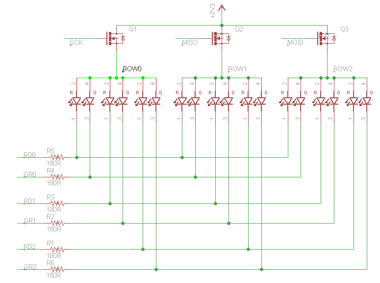
A prototype for the latest Star Ring. Q1, Q2, and Q3 use this N-channel MOSFET. The circuit runs from a 3V battery. When one of the transistors is turned on, the six red/green LEDs in the associated row can be turned on or off using six microcontroller outputs. At least that’s the theory. I built this, and it works – barely. The LEDs are extremely dim. Why?
Hint: what gate voltage is needed to turn on the transistors?
I’m not sure if there’s any way I can patch this, without having to redesign a new board.
Read 8 comments and join the conversationAtmel ICE Wiring Horror
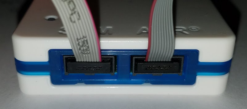
The Atmel ICE programmer/debugger has its SWD connector pins reversed from the standard ARM Cortex debug connector. Arghh… why? It’s the same physical connector (5×2 0.05 inch polarized male), but the pins are rotated 180 degrees from the standard, as if the cable were plugged in backwards. Incredibly, it also ships with a 180-degree reversing cable, so it works – as long as you use their cable. It’s not a mistake: the product is actually designed around a reversed connector with an un-reversing cable.

WHO BUILDS A PRODUCT THIS WAY?? I shake my fist at you, Atmel hardware designer. This is like designing an electric outlet where 110V and ground are swapped from their normal locations, but bundling it with an appliance cord that unswaps them.
The problem began when I grew tired of Atmel’s tiny 4-inch cable, and decided to get a replacement cable. Naturally I used a standard 10-pin ribbon cable with 5×2 0.05 inch connectors on each end: Adafruit’s purpose-made SWD cable for ARM development. I couldn’t understand why it didn’t work, and why strange things happened when it was plugged in.
After scratching my head for a while, I noticed something odd. The title photo shows both the original cable and the Adafruit cable connected to the Atmel ICE. Notice how one has the red stripe on the right, and the other on the left? Ouch!
From looking at the original Atmel cable, it’s not at all obvious that the pins are reversed. It looks like a straight-through cable, because each connector is crimped straight on to the 10-pin ribbon, with no crossing wires. But a more careful inspection reveals that one of the connectors is crimped on so it’s facing the opposite direction of the other, resulting in a 180-degree rotation of the pin assignments. It violates the rule of the cable’s red wire indicating the location of pin 1. (Ignore the extra 6-pin header, which is used for other devices)
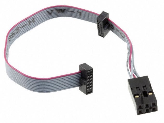
The good news is that there’s no permanent damage to my ARM board. The bad news is that I still need a replacement cable, but now I need to build a reversing one.
Read 15 comments and join the conversationWhere Did All The Watts Go?

How efficient is a typical 5V AC-to-DC power supply? I’m digging through my box of assorted power supplies from past projects, looking for something appropriate for a large LED matrix, and noticed the one pictured above. 110V 0.8A input – that’s 88 watts. 5V 4A output – that’s 20 watts. Is the power supply really only 22.7% efficient, or is my reasoning flawed somehow? I would have expected a switching power supply like this one to have much better efficiency than that. A quick search for information on “level IV power supplies” suggests they must be 85%+ efficient, so something doesn’t add up.
Read 12 comments and join the conversationLimiting SD Card Inrush Current
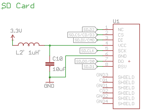
I’m experimenting with methods to limit the inrush current when an SD card is inserted, and beginning to wonder whether my solutions are worse than nothing.
When an SD card is inserted into a board that’s already powered on, a large amount of current will flow briefly, as the card’s internal capacitors are charged through its 3.3V supply pin. This is called inrush current. If the inrush current is too large, it can overtax the main board’s voltage regulator and capacitors, causing the board’s supply voltage to drop temporarily. If the voltage drops far enough, it may cause the board’s microcontroller to do a brownout reset. That’s what happened with early versions of the Floppy Emu. It wasn’t really a problem, because you’ll almost always want to perform a reset anyway after inserting a new card, but it was slightly annoying.
In later versions of the Floppy Emu, I added a 1 uH inductor and 10 uF capacitor for the SD card, as shown in the circuit schematic above. Later the capacitor was changed to a 33 uF tantalum. The purpose of the inductor was to limit the inrush current, preventing the main board’s supply voltage from sagging and causing a brownout. And it worked, mostly, as confirmed by observing the main supply and SD card supply voltages on a scope during card insertion. The exact behavior depended on the brand and type of SD card and the card’s internal circuitry. Some types of cards still caused a brownout reset when hot-inserted, but it was rare.
Revisiting this question again recently, I noticed that the inductor created a new issue that may be worse than the one I was trying to solve. When the SD card is inserted, its 3.3V supply pin doesn’t go cleanly from disconnected to connected. Instead it bounces and wiggles over a period of microseconds to milliseconds, just like the contacts of a mechanical switch. As a result, the inrush current isn’t one single burst, but a series of short on/off current pulses. Because of the presence of the inductor in the circuit, these pulses create voltage spikes on the SD card’s 3.3V supply pin. They’re brief – lasting about 100 ns – but some of the spikes go above 4V. Despite their brevity, I’m wondering if they’re high enough to damage the SD card.
Using an inductor seems to be a pretty standard solution for SD card inrush current, but I’ve never seen any discussion of the voltage oscillation and spikes this can cause for the card’s supply. An alternative is a power management IC with “soft start” behavior, but I’m not interested in adding extra chips in this case. I’m starting to think it may be best to remove the inductor, and connect the card’s 3.3V supply directly to the board’s 3.3V supply. Better to cause a nuisance brownout due to high inrush current, than to risk damaging the card with voltage spikes – and still have brownouts sometimes anyway. Have you ever dealt with this topic? How did you address it?
Read 16 comments and join the conversationLED PWM Without Resistors
I’ve been working on version 3 of Star Ring, my fun but useless circular LED blinker, and I had an idea. Do I really need current-limiting resistors for the LEDs? Or can I effectively control the LED current using PWM?
Normally a resistor is always needed in series with an LED. Without the resistor, a very high current would flow, destroying the LED. The max DC forward current is specified in the LED datasheet, and is typically something like 30 mA. Often the datasheet will also specify a peak forward current, higher than the DC max, for applications where the LED is rapidly switched on and off with PWM. But how can I calculate what the current will be, if there’s no resistor? As usual, the answer is in the datasheet.
Star Ring is an ATTINY84A microcontroller powered by a 3V CR2032 watch battery. For the sake of this analysis, we’ll assume I’m using this Lite-On dual-color LED with independent red and green elements. The datasheets for the microcontroller and the LED both include graphs of voltage vs current:
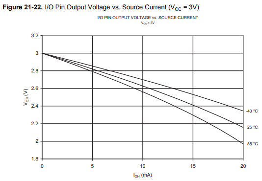

The more current that’s drawn from an ATTINY I/O pin, the more the voltage will sag below the 3V supply. And the more current that’s passed through the LED, the more the voltage across it will rise. At some point these two graphs will intersect. You have to exchange the X and Y axes of the LED graph, and extrapolate the ATTINY graph a little, but for the green LED the crossing point is about 2.0V at 25 mA. In the absence of any current-limiting resistor, that’s what you’ll get – theoretically.
25 mA is below the LED’s 30 mA max current rating, so that’s fine. It’s also below the ATTINY’s 40 mA max current per I/O pin, so that’s fine too (although it’s curious why the ATTINY IV graph only goes up to 20 mA). So for this combination of hardware, it looks like current-limiting resistors aren’t needed at all. If 25 mA is more current than is desired, PWM can be used to reduce the average current to something lower.
In reality, the DC current without a resistor will be lower than 25 mA, because of the internal resistance of the CR2032 battery, which I’ve estimated is something like 13 ohms. At 25 mA, even with a fresh 3V battery, the supply voltage to the ATTINY will only be 2.675V due to the battery internal resistance. The I/O pin output voltage will sag further below 2.675V, and those two IV curves will cross at a different point with a current lower than 25 mA. A simple experiment could find the exact number.
Ignoring My Own Advice
Despite this conclusion, I’m probably going to keep the current-limiting resistors, for a few reasons. The graph for the red LED is different than the green, and the no-resistor current will be higher, potentially at an unsafe level. I’m also uncertain whether 25 mA is really OK for the ATTINY – it’s below the 40 mA absolute max rating, but the rest of the datasheet implies 20 mA is the recommended maximum, and there’s no max continuous vs peak current distinction I can see for the I/O pin. I’m also concerned about what happens during debugging or a software crash when my PWM code unexpectedly stops running, and the LED is left constantly on until I can manage to do a reset or kill the power. The resistors will provide some valuable insurance, even if they’re not absolutely required.
Read 1 comment and join the conversation

