64 x 32 LED Matrix Programming

Everybody loves a big bright panel of LEDs. Way back in 2011, my daughter and I hand-built an 8 x 8 LED matrix Halloween display. More recently I’ve been playing with a 64 x 32 RGB matrix that I purchased on eBay for $26. Each point in the matrix is 3 independent red, green, and blue LEDs in a single package, so that’s 6144 total LEDs of awesomeness. Wow! Similar but smaller 32 x 32 and 32 x 16 RGB matrixes are also available from vendors like Sparkfun and Adafruit, so LED glory is within easy reach.
But wait, how do you control this thing? Is there a simple “hello world” example somewhere? I couldn’t find one. Adafruit has a nice Arduino library, but it’s much more complex than what I was looking for, so the basic details of controlling the matrix are lost in a sea of other code about PWM modulation, double-buffering, interrupt timing, gamma correction, color space conversion, and more. Great stuff, but not a good “how to” example for beginners. There’s also a Raspberry Pi library by Henner Zeller that’s incredibly rich, supporting video playback and other advanced features. But I really just wanted a couple of dozen lines of code to support a basic setPixel() interface, so I wrote one myself.
How is this LED matrix code different from the Adafruit and Henner Zeller libraries? It’s intentionally primitive, and serves a different purpose, for a different audience:
- Under 100 lines of code: easy to understand how it works.
- No hardware dependencies – easily portable to any microcontroller.
- Basic setPixel() interface. No fonts, lines, etc.
- 8 basic colors (3-bit RGB) only. No PWM for additional colors.
- Requires only 1 KB RAM for 64 x 32 matrix.
Controlling the Matrix
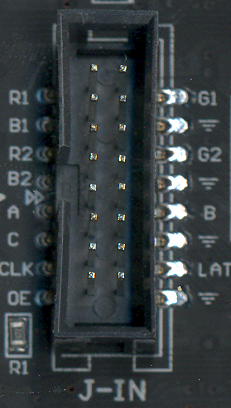
All the different varieties of LED matrixes have the same style of 16-pin connector for the control signals:

Larger matrixes like mine will also have a “D” input that replaces one of the ground pins. So what do these signals do?
OE – Active low output enable. Set this high to temporarily turn off all the LEDs.
CLK – Clock signal used for shifting color data into the matrix’s internal shift registers.
LAT – When high, data in the shift registers is copied to the LED output registers.
A, B, C (and maybe D) – Selects one of 8 (or 16) rows in the matrix to illuminate.
[R1, G1, B1] – Color data for the top half of the matrix.
[R2, G2, B2] – Color data for the bottom half of the matrix.
A matrix like this one can’t turn on all its LEDs simultaneously – only one row is on at a time. But by cycling through the rows very quickly using the A/B/C inputs, and changing the color data at the same time as selecting a new row, it can fool the eye into seeing a solid 2D image. There’s no built-in support for this row scanning, so the microcontroller that’s generating the matrix inputs must continuously refresh the matrix, cycling through the rows and updating the color data. Any interruption from another calculation or microcontroller task will cause the LED image to flicker or disappear.
Internally the matrix can be imagined as a big shift register (or actually several shift registers in parallel). The shift register size is equal to the matrix’s width. For a 64-wide matrix, the microcontroller shifts in 64 bits of data, generating a positive CLK edge for each bit, and then strobes LAT to load the shift register contents into the LED output register. The LEDs in the currently-selected row then turn on or off, depending on the data that was loaded.
Because each row contains 64 independent red, green, and blue LEDs, three independent shift registers are required. The serial inputs to these shift registers are R1, B1, and G1.
But wait – there’s one more important detail. Internally, a W x H matrix is organized as two independent matrixes of size W x (H / 2), mounted one above the other. These two sub-panels share the same OE, CLK, and LAT control inputs, but have independent color inputs. R1, G1, B1 are the color inputs for the upper sub-panel, and R2, G2, and B2 are for the lower sub-panel.
Putting everything together, we get this recipe for controlling the matrix:
2. Initialize a private row counter N to 0.
3. Set R1,G1,B1 to the desired color for row N, column 0.
4. Set R2,G2,B2 to the desired color for row HEIGHT/2+N, column 0.
5. Set CLK high, then low, to shift in the color bit.
6. Repeat steps 3-5 WIDTH times for the remaining columns.
7. Set OE high to disable the LEDs.
8. Set LAT high, then low, to load the shift register contents into the LED outputs.
9. Set ABC (or ABCD) to the current row number N.
10. Set OE low to re-enable the LEDs.
11. Increment the row counter N.
12. Repeat steps 3-11 HEIGHT/2 times for the remaining rows.
Using this method, each pixel in the matrix is defined by a 3-bit color, supporting the 8 basic colors red, green, blue, cyan, magenta, yellow, black, and white. It’s certainly possible to create more colors by using PWM to alter the duty cycle of the red, green, and blue LEDs, but this quickly becomes complex and too CPU-intensive for your average Arduino. The Adafruit library squeezes out 12-bit 4/4/4 color, but it’s hard-coded for only the Arduino Uno and Mega. I chose to keep my example code simple and skip PWM, so the color palette is limited but it’ll run on any ATMEGA (or really on any generic microcontroller).
This method is appropriate for displaying a static image that was previously drawn into a memory buffer. It won’t work for animated images, because the code for updating the animation would need to be interleaved somehow into the code for refreshing the matrix. If you need animation, you’ll need to perform steps 3-11 inside an interrupt service routine that’s executed at roughly 3200 Hz (or 200 Hz times HEIGHT/2). Anything slower than that, and the human eye will begin to perceive flickering.
Here’s my example code using the above method. It refreshes the matrix as quickly as the CPU allows, and provides a very basic setPixel(x, y, color) API. The code was written for a 16 MHz ATMEGA32U4, but it doesn’t use any ATMEGA-specific hardware features, and should be easily portable to any other microcontroller with at least 2 KB of RAM.
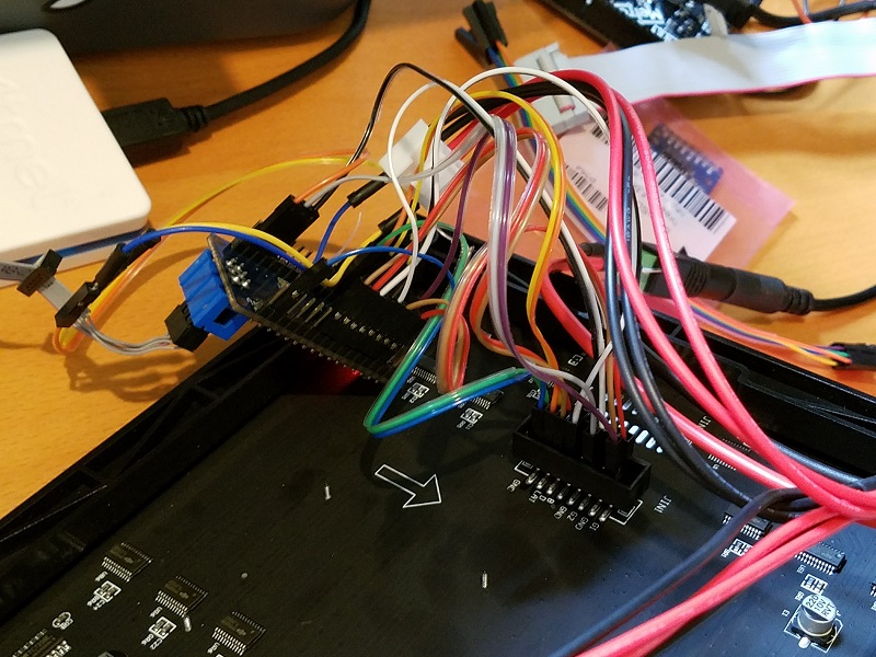
My hardware was an ATMEGA32U4 breakout board, connected to the LED matrix with lots of messy jumper wires (this is Big Mess o’ Wires after all). Fortunately the mess is mostly hidden behind the display, but a custom-made adapter or cable would certainly be cleaner. Here’s a peek at the back side:

I discovered one odd behavior that may be specific to this particular LED matrix: if you don’t cycle through the rows quickly enough, the matrix won’t display anything. It doesn’t work if you set the row number (ABCD inputs) to a fixed value for testing purposes, as I did in my initial tests. It took a huge amount of time for me to discover this, and I haven’t seen this behavior documented anywhere else. From my experiments, if you spend more than about 100 ms without changing the ABCD inputs, the display shuts off. Maybe it’s some kind of safety feature.
Displaying a Bitmap Image
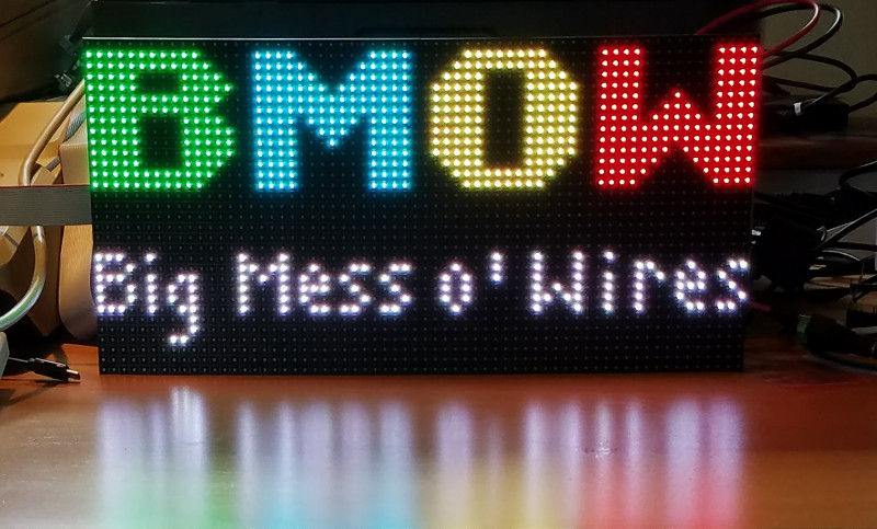
Maybe you’re wondering how I rendered the BMOW logo in the title photo? I certainly didn’t write a bunch of code that calls setPixel() thousands of times – that would be painful. Instead, I used GIMP to export a 64×32 image as a C header file, and then wrote some glue code to parse the data and call setPixel() as needed. Here’s how you can do it too.
First you’ll convert your image to indexed color mode.
2. Select the menu Image->Mode->Indexed.
3. In the conversion dialog, select “Generate Optimum Palette”. Set the maximum number of colors to 256.
4. Click the button “Convert”.
Now you can export the converted image as a C header file.
2. In the save dialog, set the export type to “C source code header (*.h)”
3. Click the button “Export”.
Open the generated header file in a text editor. You should see a section that begins with data like:
static char header_data_cmap[256][3] = {
	{  0,  0,  0},
	{244, 38,117},
	{ 28,239,250},
	...
and a second section that begins like:
static char header_data[] = {
	0,0,0,0,0,0,0,0,0,0,0,0,0,0,0,0,
	3,3,3,3,3,3,3,3,3,3,3,0,0,0,0,0,
	...
For the Arduino or ATMEGA microcontrollers with limited RAM, these declarations must be modified to store the data in program memory (flash ROM) instead of in RAM. Other microcontrollers can skip this step.
For both of the above sections, change static char to const unsigned char, and add PROGMEM just before the = sign:
const unsigned char header_data_cmap[256][3] PROGMEM = { ...

const unsigned char header_data[] PROGMEM = { ...
Then use the function LoadROMImage() to read the bitmap data and set the corresponding pixels in the LED matrix framebuffer. Here’s the updated example code:
led-matrix-bitmap.c
bitmap-data.h
The bitmap data is palettized color, where each palette entry is a color with 8 bits of red, 8 bits of green, and 8 bits of blue. LoadROMImage() just uses the most significant bit of each color channel to select the 3-bit color for the LED matrix framebuffer. If you want something fancier, you could try some kind of error-minimization code for selecting the 3-bit color instead. But if you care strongly about attractive-looking colors, then you should probably use Adafruit’s PWM library or something similar, instead of this code.
Footnote: I struggled to get a good-looking photo of the LED matrix. It’s very bright and sharp, with deeply saturated colors. But regardless of what camera settings I tried for shutter speed, ISO, and white balance, I got a muddy desaturated mess like the photo seen above. Judging by the other photos of this matrix that I found on the web, I’m not the only person to find the photography challenging.
If the example code here was helpful, or you built something interesting using it, please leave me a note in the comments. Thanks!
Read 3 comments and join the conversation3 Comments so far
Leave a reply. For customer support issues, please use the Customer Support link instead of writing comments.


Wow, would be great to see a video as well!
In an LED datasheet you’ll find both a maximum “DC forward current” and a “peak forward current”. Typical values for these might be 25 mA and 100 mA, respectively. If you want to just light up the LED and leave it on, you should use the DC forward current specification.
However, if the LED is part of a multiplexed scheme where the LED is only on 10% (or whatever fraction) of the time, it’s going to appear much dimmer than it would if it were on 100% of the time. This is where the “peak forward current” specification comes into play. Essentially, you are allowed to drive the LED much harder than usual, to make it brighter than usual, to compensate for it actually being off most of the time thus bringing the average brightness up to something closer to what you would see if it were on continuously at the DC forward current level. The datasheet should have a footnote for the peak forward current stating the maximum duty cycle and pulse time, so that the LED has sufficient time to dissipate the extra waste heat and not burn up.
I expect that your display’s unstated requirement to cycle through the rows fast enough is indeed a safety feature so that the LEDs are not driven at the peak forward current continuously.
I have cured the problem with the newer 64×32 panels for use with an Arduino: http://bobdavis321.blogspot.com/2019/02/p3-64×32-hub75e-led-matrix-panels-with.html