Archive for February, 2018
Floppy Emu Display Experiments
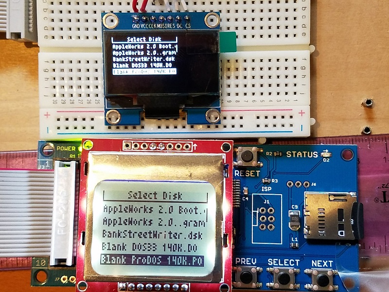
Last week I wrote about my troubles with the Nokia 5110 LCD used by Floppy Emu, with a discussion of possible replacements. There was no clearly obvious alternative, as most of the options were too big, too small, too expensive, not available from a reliable supplier, or had some other shortcoming. After some thought, I settled on the 1.3 inch OLED as the most likely alternative. And now, after hacking away on the Emu’s firmware, I have a working example of a Floppy Emu with this 1.3 inch OLED display.
Nokia 5110 Clone LCD: 1.4 inch diagonal display, mounted on a carrier PCB, 84×48 pixels, SPI interface, 1-bit graphics
No-name OLED: 1.3 inch diagonal display, mounted on a carrier PCB, 128×64 pixels, SPI interface, 1-bit graphics
The photo shows a head-to-head comparison between the old and new displays. The picture doesn’t do the OLED justice – although it looks blurry here, it’s actually very crisp and pleasant to look at. The only significant problem is the tiny pixels, which makes the text a bit difficult to read. Although the display diagonal isn’t much smaller than the Nokia LCD (1.3 inch vs 1.4 inch), the aspect ratio is different, and the OLED’s height is only 2/3 the Nokia’s height. Then the OLED packs 1.33x as many vertical pixels as the Nokia, so the OLED actually has 2x as many dots per inch. You can see in the photo, when drawn with the same number of pixels, the OLED text is only half as tall as the Nokia text. Get out your reading glasses.
It’s not too bad, and I could probably live with text this size, but it’s not ideal. It would be great if I could simply make all the text 1.33x taller to take advantage of the OLED’s extra resolution, but unfortunately it’s not that simple. Text needs to be a whole number of pixels tall, and with the Nokia LCD there are six rows of 8 pixel tall text. The most I could increase this with the OLED would be 10 pixel text, 1.25x taller, for 60 pixels total, leaving 4 pixels wasted. But 10 pixel text is an awkward number, because the OLED’s command interface is built around the concept of “pages” that are 8 pixels tall. If text spans a fractional number of pages, I’ll need to completely redo the way display updates are performed, and maintain a framebuffer of the whole display area. Unless I get really fancy (dirty rectangles anyone?), that will require re-sending all 128×64 pixels of the framebuffer to the display every time I draw anything. That will be noticeably slow, which is one of the things I wanted to avoid.
So instead of making the text taller, I’ll probably make it wider. That should help a lot with readability. With 6×8 pixel characters, I’ll get 8 rows of 21 characters each, compared to 6 rows of 21 4×8 pixel characters on the Nokia LCD. Two extra rows of text will be nice.
I still need to look at the power consumption of the OLED as compared to the Nokia LCD. When I have two Floppy Emus powered by a single 5V USB supply, the one with the OLED glitches and resets whenever I turn on the one with the Nokia LCD. I’m not sure what’s causing that, but it doesn’t happen with two Nokia LCDs.
The final hardware headache will be modifying the Floppy Emu PCB layout. In order to keep the OLED centered, I need to relocate the LCD header into a spot that’s currently packed with traces and chips. I’ll also need to move the header from the bottom section of the board to the top (unless I mount the OLED upside-down), which means running several new traces across the full height of the PCB, or just redoing the entire board layout, which doesn’t sound fun. I’ll probably want some kind of mechanical support for the bottom end of the OLED too, since the OLED only has pins along its top, and it tends to hinge downward from those pins by force of gravity. That’s not a deal-breaker, but it looks a bit unattractive.
There will be some software challenges to address as well. I can’t just replace all the Nokia 5110 code with OLED code, because then future versions of the Floppy Emu firmware won’t work on all the Emus out in the world now with Nokia LCDs. I don’t want to maintain two different versions of the firmware either, one for each display type. Ideally I’ll find a way to create a single firmware that knows how to control both types of displays, and can dynamically detect which one is present.
The OLED display costs about twice as much as the Nokia LCD, but it’ll be worth it if it eliminates the headaches I’ve had with the Nokias. Right now I don’t expect I’ll need to change the price of the Floppy Emu. I’ll see how things look once everything is finalized.
Read 7 comments and join the conversationMore Yellowstone Trouble

I did some surgery on the Yellowstone board, in an attempt to address major problems with power supply noise and data bus overshoot, previously discussed here and here. I replaced the 74LVC245 that drives the data bus with a 74LVC8T245. That’s a dual-supply chip that some readers suggested earlier: it ensures the bus outputs will drive all the way up to 5V, while hopefully reducing any noise coupled to the 3.3V supply, and avoiding the possible violation of limiting values with the 74LVC245 that I mentioned in my last comment to the previous blog post. The Yellowstone board still mostly works with the 74LVC8T245, but now the data bus overshoot climbs to a whopping 9 volts! Arrrrgh.
Channel 1 (yellow) is a copy of the Apple II slot’s /IOSELECT signal, passed through the FPGA. When it goes low, it means the Apple II wants the card to drive the bus.
Channel 2 (light blue) shows D0 on the data bus, with a nasty overshoot.
Channel 3 (pink) is an internal active-high debug signal from the FPGA that shows when it’s outputting a value for the 74LVC8T245 buffer. This is a sanity check on what’s happening.
Channel 4 (dark blue) shows the Yellowstone card’s ground, with respect to the Apple II system ground. Note there’s about 1V of peak-to-peak ground noise.
Something is badly wrong, and I can’t find it. I could design a new board with some series termination resistors, as a few people suggested, but my intuition is that isn’t really the main problem. None of the other Apple II cards I’ve examined appear to use any termination at all. 9V is a massive overshoot. And termination issues wouldn’t explain the problems observed on the card’s 3.3V power and GND supplies. I feel like I’m headed down the wrong path.
I’ll probably ice this project for a while, since enthusiasm for further debugging has run out. On to something else…
Read 9 comments and join the conversationQuest for a Decent LCD
Floppy Emu uses an 84×48 graphical LCD display. It’s just a low-resolution 1-bit display, but it’s fast and easy to use, and has a nice built-in backlight. The display is actually a clone of the old Nokia 5110 phone display, and it’s made by semi-mysterious third-party factories in Shenzhen. It can be purchased in bulk for about $2.50 apiece. Photo from RH Electronics.
The big problem with these Nokia 5110 displays is that their reliability stinks. The actual LCD module (the glass and metal bit) is clipped onto a supporting PCB with some passive electronics, and it’s only a pressure-fit holding the two together. If it’s not clipped in just right, the display will exhibit contrast problems, or glitchy behavior, or just won’t work at all. Gently pushing on the LCD frame sometimes changes the pressure-fit enough to make these problems appear and disappear. Adjusting and tightening the LCD clips, as described in the Floppy Emu manual, is the only thing I’ve found that helps.
The electronics assembler that builds Floppy Emus must go through every LCD to check for problems. They usually end up discarding about 10% of all the LCDs, because they don’t work no matter how the clips are adjusted. Once the boards are finished, I do a second check of each LCD immediately before it’s shipped to the customer. This often requires more fiddling with the clips, or manual contrast adjustments, and a further 5% of LCDs are discarded. It’s very time-consuming, but despite all this effort, some troublesome LCDs still reach customers who must then make further adjustments.
In the most recent batch of LCDs, the pressure-fit contact design changed slightly, and it now appears to be even more troublesome than before. At the same time, the LCD bezel was unexpectedly enlarged by 2mm, forcing me to redesign the Floppy Emu acrylic case to match. This is a risk of buying generic parts from eBay and Alibaba, with no manufacturer to stand behind them or datasheet to document them.
Surely There Must Be Something Better?
It would be very nice to replace the 5110 displays with something similar but more stable. A replacement would need to handle about 84 x 48 1-bit pixels (equivalent to 21 x 6 text characters), with a diagonal size about 1.5 inches, and ideally use an SPI interface. Unfortunately, I’ve found nothing that even comes close. The alternatives are either much too large/small, lack graphical capabilities, are too slow, or are much too expensive.
Character and numeric displays aren’t appropriate, since they can’t do graphics or six rows of text. So looking at Digikey’s Display Modules – LCD, OLED, Graphic category, and sorting by unit price quantity 100 purchasing, and including only those results that have at least a few hundred units in stock, I found these:
128×128 RGB LCD, 1.44 inch diagonal, $4.23 – This could almost work, except I believe it’s a 24-bit color display, so the microcontroller would need to move 24x as much data to draw on it. And because it’s a much higher resolution, the amount of data to moved must be still higher to maintain the same font sizes as the old display. And it’s a slow I2C interface, instead of fast SPI. And there’s no datasheet.
128×32 LCD, $8.01 – This is an odd shape, doesn’t have enough vertical resolution, and uses a parallel 8-bit interface.
Another 128×32 LCD, $8.69 – Also an odd shape, and not enough vertical resolution.
128×160 RGB LCD, 1.8 inch diagonal, $8.83 – This is another color, higher-resolution display like the $4.23 one, but it uses a parallel interface.
128×64 LCD, 2 inch diagonal, $9.52 – Too big, too expensive, uses a parallel interface.
Non-Branded Options
Nothing from DigiKey looks suitable. What about other options from eBay or Alibaba?
128×64 OLED, 0.96 inch diagonal, $2.91 – This could sort of work, and I have one of these modules already. But it’s tiny, smaller than a postage stamp, which isn’t really suitable. It’s also I2C which means the interface is comparatively slow. Coming from a random non-branded eBay seller, it’s also not clear it would be any more reliable than the LCD display I have now.
128×128 RGB LCD, 1.44 inch diagonal, $3.04 – This is basically the same as the $4.23 module from DigiKey. Although this one says it has an SPI interface. Maybe this is the best option from a list of not-so-great alternatives.
Read 12 comments and join the conversationYellowstone Arrgh

I’m still struggling with these Yellowstone card electrical problems, but getting nowhere. Very frustrating. I’ve focused my attention on the large amount of overshoot on the data bus, and the power supply fluctuations, under the theory that minimizing those will eliminate all the functional glitches and failures I’ve experienced.
The FPGA has eight bidirectional pins that are connected to one side of a 74LVC245 buffer. The other side is connected to the data bus. The buffer’s direction is controlled directly from the CPU’s R/W signal, and the buffer’s output enable is controlled by FPGA logic. The FPGA pins direction are controlled by separate FPGA logic. See the schematic here.
The image above shows the moment when the card starts to drive a value on the data bus.
Channel 1 (yellow) is a copy of the slot’s /IOSELECT signal, passed through the FPGA. When it goes low, it means the Apple II wants the card to drive the bus.
Channel 2 (light blue) shows D0 on the data bus. Notice how it climbs from 0 to 2V, retreats back to near 0, shoots up to 4.6V (a good trick for a 3.3V chip), and finally settles at 3.3V? Yuck.
Channel 3 (pink) is an internal active-high debug signal from the FPGA that shows when it’s outputting a value for the 74LVC245 buffer. This is a sanity check on what’s happening.
Channel 4 (dark blue) shows the Yellowstone card’s ground, with respect to the Apple II system ground. Note the scale: it doesn’t look like much, but there’s almost 1V of peak-to-peak ground noise.
Besides the data bus overshoot, there’s also something odd with /IOSELECT on channel 1. Because there’s no convenient place for me to physically probe the actual /IOSELECT signal, I used an FPGA debug output pin to mirror /IOSELECT and capture it with the scope. The result should look identical to the actual /IOSELECT, except shifted to 3.3V logic levels rather than 5V, and with a few nanoseconds of extra delay. But why is there 1V of undershoot on the scope when /IOSELECT first goes low? The scope is capturing a debug output that’s just a two-inch trace on the Yellowstone card, with no other load except the scope probe. I was not expecting to see any undershoot or overshoot on these debug signals, and the channel 3 (pink) debug signal doesn’t show any.
As bad as that scope trace looks, this one looks worse:

This looks like some kind of glitch, because the FPGA is only outputting for about 60ns, but a normal output lasts about 500ns. /IOSELECT starts to fall, but then goes back up, and shoots up to 5.0V (remember this is an output from a 3.3V chip). The data bus voltage spikes to 6.6V, and the Yellowstone ground reaches 2.0V relative to Apple II ground. Arrgh!
In an effort to troubleshoot this glitch further, I switched channel 2 (light blue) to show the direction of the Apple II motherboard’s data bus buffer, which should (I think) simply be the CPU’s R/W signal. This was the result:

It appears that the glitch occurs just before the end of a CPU write, when the direction switches from low to high. Assuming that’s the CPU R/W signal, that means the glitch starts during a time when R/W is 0, which should be impossible. Here’s the Verilog equation for the channel 3 (pink) signal:
assign isOutputting = (rw && ~_romoe);
If R/W is zero, then isOutputting must also be zero, but from the scope trace it’s obvious that’s false. There’s something happening here that I don’t understand. Maybe the Apple II motherboard’s data bus buffer direction isn’t driven from the CPU’s R/W, but from some other buffered or computed signal.
When I rearranged some things in an attempt to investigate the glitch further, it disappeared. I was never able to find an explanation.
Head Scratching
There are so many strange unexplained problems, it’s a miracle that the card actually works most of the time!
So what causes big overshoots and supply fluctuations? I can think of a few possibilities:
1. 3.3V voltage regulator can’t meet the instantaneous demand for current
2. Insufficient bypass capacitors on the card
3. 5V and GND connections from the card to the slot are too wimpy, and can’t carry enough current without significant resistive loss
4. Impedance mismatch on the data bus, signal reflections, etc.
Considering each of these in turn:
1. There’s a 300 mV LDO on the card, which I’ve calculated should be enough for the average demand. Brief spikes in demand should be satisfied by the capacitors. What’s the behavior of a typical LDO when it’s overtaxed? Does the regulated voltage drop, or does ground get pulled up, or both? If I make another revision of the Yellowstone board, I’ll substitute a larger regulator just to rule out this possibility.
2. My intuition pointed to this explanation first, but it hasn’t been confirmed by experiments. You can see all the bypass capacitors in the schematic: at least one 0.1 uF ceramic cap for the power supply on each chip, plus others recommended by the FPGA and LDO datasheets. I tried jury-rigging additional capacitors at various points on the board, but they didn’t make an observable difference in the signals as viewed on the scope. And even if this were the problem, I could imagine it causing the overshoot seen on the databus, but I can’t see how it would cause Yellowstone’s ground to rise to 2.0V relative to Apple II ground.
3. I tried connecting some extra jumper wires from ground points on the card to ground points on the Apple II motherboard. It didn’t make an observable difference in the signals as viewed on the scope. But maybe 5V has a problem?
4. An impedance mismatch could be part of the problem, but what would I do about it? The Apple II bus can contain anywhere from zero to six other cards of assorted types, so it’s not clear what impedance I should try to match. And all the vintage 1980’s cards I’ve observed don’t appear to have any termination resistors or other obvious impedance matching circuitry – they just connect a 74LS245 or similar buffer chip directly to the bus.
For clarity, I don’t think Yellowstone’s use of a 3.3V 74LVC245 is a problem, at least not in the way suggested by some commenters. Yes, this chip can only drive to 3.3V, but that’s plenty high enough to register as a logical high for the 74LS series logic used elsewhere in the Apple II. And the scope traces clearly show that the data bus voltages are high enough. If the 74LVC245 is causing a problem, it must be some less-obvious mechanism like coupling noise to the 3.3V supply, or maybe a too-fast slew rate.
I’ve pounded my head long enough, and am running out of ideas. Debugging is hugely impeded by the absence of any place to physically probe many of the bus signals, and by a scope with only four analog channels. The scope also has a 70 MHz bandwidth, which might be a factor. I feel too much like I’m scratching randomly in the dark, rather than making systematic progress towards narrowing down the causes of the problems.
My temptation is to design a new revision of the card, and include some speculative changes that might help. I could substitute a beefier LDO, add more capacitors, make the power connections extra-robust, and include additional debug headers for probing bus signals. It can’t hurt, but realistically it probably won’t help either. I could also try adding some termination resistors, but that just seems wrong somehow, given that no other Apple II cards appear to use them.
Electronics can be hard. In the 10 years I’ve been writing this blog, I’ve never encountered a problem that had me so completely stalled as this one.
Read 16 comments and join the conversationApple II Card Electrical Woes
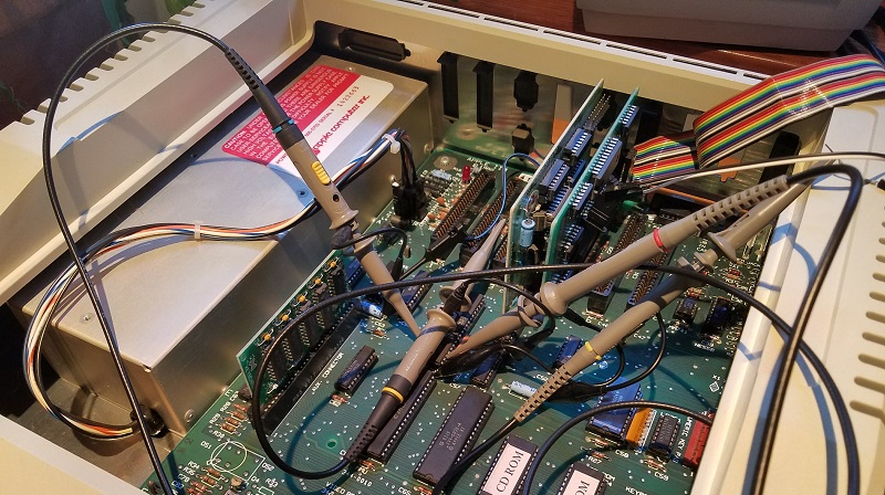
The digital abstraction of zeroes and ones is lovely, but electronics debugging often requires a deeper look into the realm of analog signals. That’s the story of my Yellowstone FPGA-based disk controller for Apple II, and it’s slowly driving me crazy. Those nice clean zeroes and ones are gone, and instead I’m struggling with voltages, logic thresholds, capacitance, and power in an attempt to explain what’s going wrong.
This story begins 12 days ago, the first time I successfully booted my Apple II using the Yellowstone card. With Yellowstone configured to clone a Liron disk controller, I was able to boot from a Unidisk 3.5 drive as well as from a Floppy Emu in Smartport emulation mode. Success! But the excitement was short-lived: it only worked when Yellowstone was the only card installed in the Apple IIe. With another card present, the computer would crash into the system monitor during power-up about 90% of the time. With more investigation, I gathered these clues:
- it didn’t matter what the other cards were
- it didn’t matter what slots the cards were in
- the crash occurred even when no disk drives were attached – so it’s unrelated to the drive or the disk contents
- the crash occurred in an Apple IIe and an Apple IIgs
- in the Apple IIgs, crashes were more likely to occur as the number of other cards increased
Based on this, I suspected some kind of electrical problem as opposed to a logic design problem. More cards means more capacitance on the data bus: maybe the Yellowstone output driver wasn’t able to switch the bus signals fast enough? More cards also means more load on the data bus: maybe the Yellowstone output driver wasn’t able to source or sink enough current to maintain a valid logic high or low voltage?
With a logic analyzer, I examined the pattern of card accesses during good and bad power-up sequences. During a normal boot, there’s a 93ms period of near-continuous Yellowstone ROM access, which is probably running the ROM code to look for an attached drive. During a boot-up where the computer crashes, this ROM access lasts a much shorter random-seeming amount of time. I measured times of 0.19ms, 1.57ms, and 28.5ms. From this I concluded that the crash is happening during execution of the Yellowstone ROM code, rather than the Yellowstone card somehow causing an error with another card or with the Apple II itself.
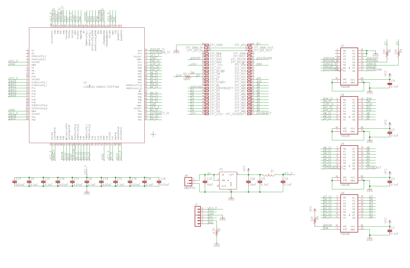
Some hardware background: shown above is a simplified schematic of the card (click for a hi-res version). The FPGA runs at 3.3V, powered from a Micrel MIC5504-3.3YM5-TR LDO regulator. A set of four 74LVC245 chips provide 5V to 3.3V level translation. Three of the chips are configured for unidirectional signals like the address bus and control signals, and the fourth is bidirectional for the 8-bit data bus. Each 74LVC245 has a 0.1 uF ceramic bypass capacitor about 2 mm from its VCC pin. The FPGA has twelve 0.1 uF ceramic bypass capacitors for each of its power/ground pin pairs, and its 3.3V supply is isolated from the rest of the board’s 3.3V supply with a ferrite bead, as recommended in the FPGA datasheet. There are also 10 uF ceramic capacitors on the input and output of the LDO.

So… where to begin troubleshooting? Based on suggestions from helpful commenters on a previous post, I used a scope to measure the Yellowstone card’s GND and 3.3V relative to a ground point on the Apple IIe motherboard. They both looked pretty noisy, with peak-to-peak oscillation of 680 mV for Yellowstone’s ground and 460 mV for 3.3V, at the moment Yellowstone begins to drive the data bus. But surprisingly I also observed virtually the same oscillation when Yellowstone was *not* driving the data bus and the Apple II was idle – shown in the trace above where where light blue is GND and pink is 3.3V. Then for comparison I examined a standard Disk II controller card, when Yellowstone wasn’t installed in the computer. On the Disk II card, while the Apple II was idle, I measured 600 mV of oscillation on GND and 280 mV on 5.0V. I’m not sure how to explain all this, except to note that Yellowstone’s supply oscillations don’t seem dissimilar to other cards.
At this point I tried a few quick experiments:
- Adding a 47 uF electrolytic capacitor across the Yellowstone card’s 3.3V and GND supplies didn’t make any noticeable difference.
- Connecting an extra ground wire between the Yellowstone card and a ground point on the motherboard helped a lot. The frequency of crashes after reset dropped from 90% to 20%. Hmmm.
To check the data bus voltage levels and timings, I used a 4-channel scope:
- Channel 1 (yellow) – /IOSELECT – Asserted when the Apple II wants the card to drive ROM data onto the bus.
- Channel 2 (light blue) – Phi 1 – 6502 clock signal.
- Channel 3 (pink) – Phi 0 – 6502 clock signal. A read operation terminates at the rising edge of Phi 0.
- Channel 4 (dark blue) – A bit on the data bus, either D0 or D7 depending on the test.
/IOSELECT was measured at the card. Phi 0 and 1 were measured directly on the 6502. The data bus was measured at the motherboard’s 74LS245 buffer, chip UB2 on the Apple IIe motherboard.
To make a long story short, everything looked mostly fine, and I’m stumped as to why Yellowstone crashes when other cards are present. Here’s a selection of scope traces.

As a starting reference, the trace above shows a real Liron card with no other cards installed. When /IOSELECT is asserted, D0 goes high about 64 ns later. It overshoots to 4.7V before settling back to 3.8V. After the rising edge of Phi 0 and /IOSELECT is deasserted, the data bus stays high for 270 ns more. I suspect this is bus capacitance holding the old value while nothing is actively driving the bus, as opposed to the Liron card actually driving the bus beyond when /IOSELECT is deasserted.

Here’s the Liron card driving a logic low voltage on D7. The signal timing is the same as for the logic high on D0. The low voltage is about 80 mV.
I repeated both of these tests with a Liron and a Disk II card both present, and the results looked basically the same.

Here’s the Yellowstone card, with no other cards installed. The signal timing looks the same as with the real Liron card, including the 270 ns “hold period” after /IOSELECT is deasserted. D0 shows a large overshoot to 5.7V before settling back to 3.4V, which is about what I’d expect from a 3.3V card. While that’s a lower voltage than seen from the Liron card, it’s still well above the logic high threshold of 2.0V for the Apple IIe’s 74LS245 buffer.

Yellowstone driving a logic low. There’s some significant undershoot, then the voltage goes to 0V, and timing looks OK.

Now comes the interesting part: the trace above shows the Yellowstone card with a Disk II card also installed. This is the case that doesn’t work, where the computer crashes during power-up. I expected to see something wrong on the scope trace, but I didn’t. It looks very similar to previous test with Yellowstone by itself. The signal timing is the same. The high voltage overshoots to 5.4V before settling back to 3.3V.

Finally, here’s the Yellowstone card with a Disk II card also installed, driving a logic low. The bus voltage goes to 0V. It looks the same as the case when no other cards are installed.
So what now? The only thing that looks maybe concerning in these traces is the large amount of overshoot from Yellowstone when driving a logic high voltage. But the overshoot is actually less severe when a second card is installed, not more severe, which doesn’t fit the pattern of more cards leading to more crashes.
Maybe the bus voltages are only bad at certain moments, when a specific value is driven onto the bus, or some particular combination of control signals occurs? That’s possible, as my test was only able to capture the very first access to card ROM during a boot-up. If there are bad voltages appearing later, I wouldn’t have seen them.
Maybe the problem isn’t bad voltages driven on the data bus by Yellowstone, but bad voltages received by Yellowstone from the data bus and from control signals? If the Yellowstone card’s ground were pulled above the Apple IIe’s ground, it would have the effect of raising the voltage threshold for Yellowstone to receive a logic high, and cause it malfunction if signals were received incorrectly. This might explain why attaching an extra ground wire seemed to help. But from what I’ve seen of the logic signals from the Apple IIe, they’re in the 3.8V and above range, which is significantly higher than the 2.0V threshold of Yellowstone 74LVC245 buffers, even when allowing for a few hundred millivolts of ground differential.
Maybe I’m wrong about this being an electrical problem at all, and despite the circumstantial evidence, it’s actually some kind of logic bug?
Read 37 comments and join the conversationMac ROM-inator II Sale!
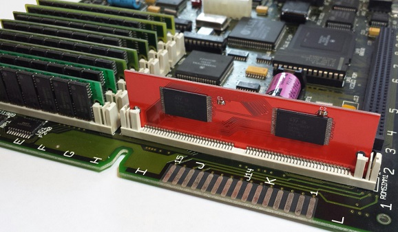
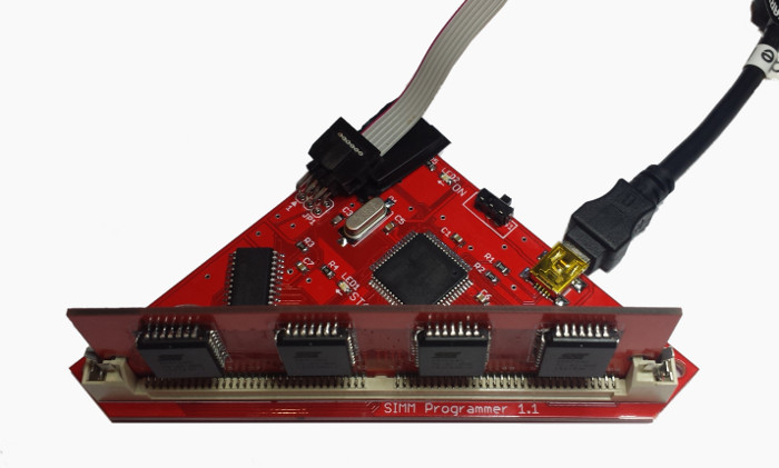
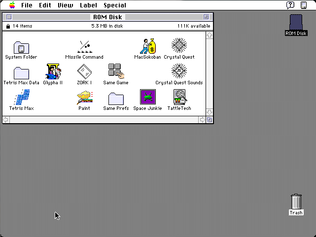
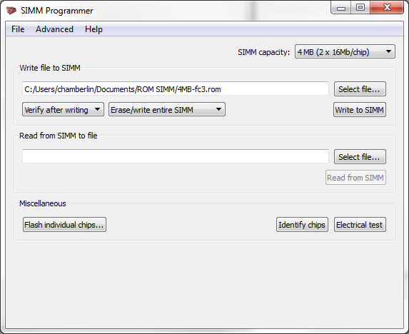
Want to add new features to your old Mac? The Mac ROM-inator II hardware for vintage Macintosh is on sale at a special price for a limited time. The ROM-inator II SIMM replaces the stock Macintosh IIx, IIcx, IIci, IIfx, IIsi, or SE/30 ROM with a programmable flash memory module. Add a bootable ROM disk, change the startup chime, hack the icons, gain HD20 support and get a 32-bit clean ROM. For the ultimate in customization, you can also use the optional ROM SIMM Programmer to reprogram ROM-inator II with your own custom content. It’s a great way to breathe new life into your old II-series Mac or SE/30.
- 8 MB Mac ROM-inator II MEGA, $59 SALE! $49
- ROM SIMM Programmer, $59 SALE! $49
- 4 MB Mac ROM-inator II Standard, $36
Boasting 2x the storage capacity of the original ROM-inator II, the 8 MB ROM-inator II MEGA is on sale for $49, which is $10 off the regular price of $59. The MEGA’s default ROM disk image has been expanded with a nice collection of classic utilities and games, including ResEdit and some SCSI tools, which should be useful for anyone configuring a new hard disk. The ROM SIMM Programmer is also on sale for $49, $10 off the regular price of $59. Combining the ROM SIMM Programmer and the MEGA, you’ll have the maximum possible flash ROM space for your custom content. The 4 MB ROM-inator II “standard edition” is also available for $36.
