Archive for July, 2017
Liron Support for Floppy Emu
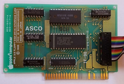
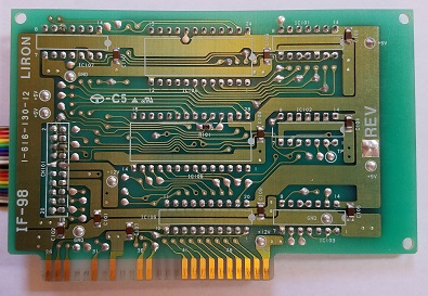
Great news for owners of the Apple II Liron disk controller card: the latest Floppy Emu disk emulator firmware adds Liron support. This means that for the first time, it’s now possible to emulate 32 MB hard disks on an Apple II+ or IIe with the Floppy Emu!
The Liron is a “smart” disk controller for the II+ and IIe, using the same Smartport protocol as the Apple IIc, IIc+, and IIgs. It was originally designed to work with the Unidisk 3.5 inch floppy drive, but other Liron-compatible third-party external hard drives were later developed. With this new firmware, the Floppy Emu is able to emulate one of these hard drives, bringing an exciting new capability to the II+ and IIe.
Smartport emulation with the Liron card works nearly identically to the IIc, IIc+, and IIgs, as described in section 10.4 of the Floppy Emu manual. Connect the Emu to the Liron card, use the Emu’s menus to select Smartport mode, and populate your SD card with up to four disk images. These will appear as four virtual hard drives connected to your II+ or IIe.
Depending on your Apple II model and its version of the autostart ROM, the Liron-connected disk may or may not automatically boot when the power is turned on. If you have an older model that doesn’t autostart the Liron, type PR#7 to get things started (or PR#N if your Liron card is in slot N).
This is new firmware, so your help with testing is appreciated. If you tried the new firmware and it worked fine, please let me know. If it didn’t work, definitely let me know. Try it in Smartport mode with the Liron of course, but also try it with the built-in Smartport of your IIc, IIc+, or IIgs to verify it still works there too, and doesn’t interfere with other types of drives that are also present in the daisy chain.
Download the new firmware here:
Floppy Emu Model A – apple-II-0.1T-F16
Floppy Emu Model B – apple-II-0.1T-F18-modelB
Pogo Pin Test Board for ADB-USB Wombat
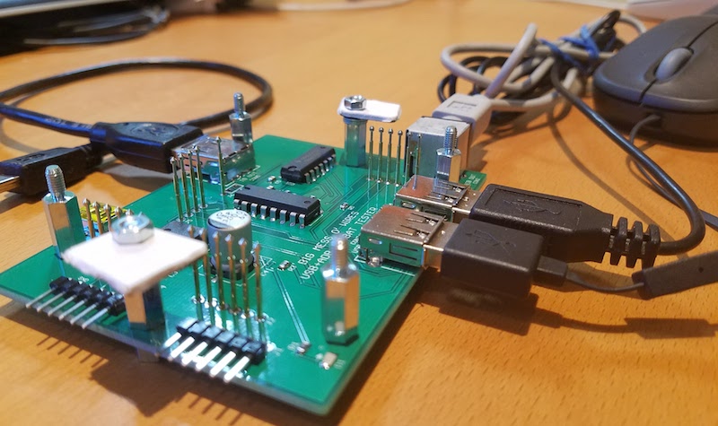
Here’s a test rig for the ADB-USB Wombat board: my first-ever project whose sole purpose is to facilitate testing of another project. It uses spring-loaded pogo pins to create a bed of nails that fit into test points on the Wombat board. I can drop a new Wombat board onto the tester, clamp it in, and then program and test it with just a few button clicks. This is a huge improvement over my old manual testing method, which involved multiple cable connections and disconnections, and hand-verified keyboard/mouse emulation on two separate computers. That sort of test process is fine for building a few units, but something faster and easier is needed to support higher volume assembly.
Pogo pins contain tiny internal springs. When a Wombat board is pushed down onto the bed of pins, they compress a few millimeters in length. This helps to create a reliable electrical contact for each pin, even if the uncompressed lengths of the pogo pins are slightly different or they’re not perfectly aligned.
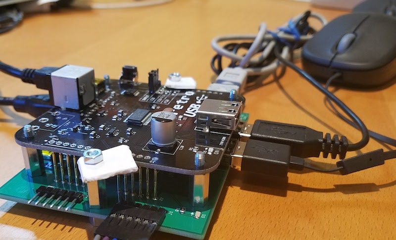
The tester has on-board ICs to open and close external loopbacks for the Wombat, so the I/O functions can be verified. It also has a power management IC that can supply the Wombat through two different interfaces, ensuring they both work. But the real value of the tester is that the power cable, PIC programmer, serial cable, ADB peripherals, and USB peripherals can all be permanently connected to the test board instead of plugged/unplugged from the Wombat for each test iteration.
Perfecting the tester took much longer than I’d expected, and it wasn’t until the third generation that it worked reliably enough to be useful. Given the size of that time investment, it’s unclear if I really achieved a net time savings, but I definitely learned a lot. Getting the mechanical aspects working smoothly was a challenge. Thinking about all the ways a Wombat could be broken was also a challenge, since I’m typically thinking about how things work instead of how they don’t work. With those possible failure modes in mind, I then needed to design circuitry to detect each failures.
If the test passes, the Wombat’s LEDs blink with a pulsing glow as shown in the video. If the test fails, the LEDs flash a variable number of times to indicate a two digit failure code. This code can be looked up on a reference sheet to see which sub-test failed, and which components are probably at fault.
Read 1 comment and join the conversationCustom Mini Case for Macintosh LC, P475, Q605
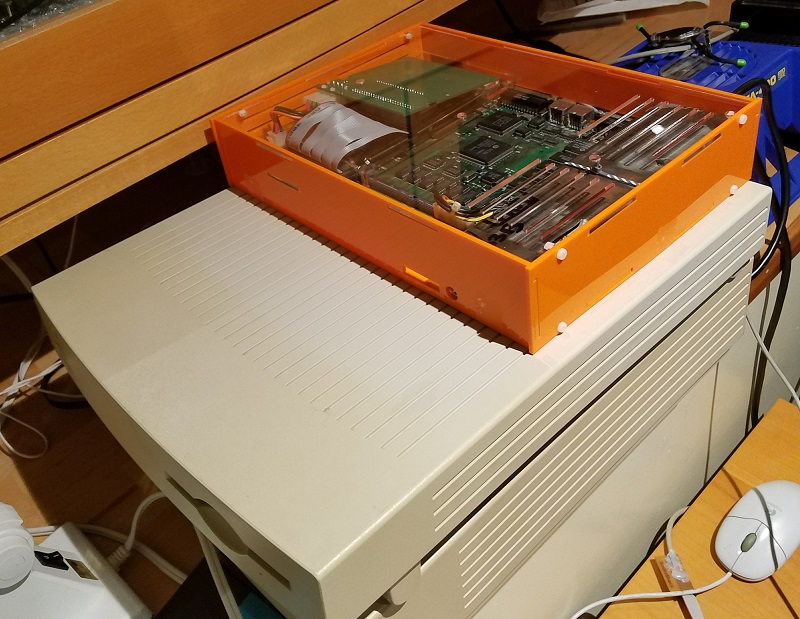
Here’s a custom laser-cut case for the Macintosh LC family, Performa 400 series, and Quadra 605. By removing the internal floppy drive and fan, and replacing the internal SCSI drive with a SCSI2SD board, I was able to make a design that’s about half the size of a standard LC case. The pieces fit together loosely with tabs and slots, and then screws and nuts in T-slots provide extra support to make everything nice and solid. The finished case isn’t much bigger than my keyboard, which is neat. Here it is outfit with a Floppy Emu and an ADB-USB Wombat:
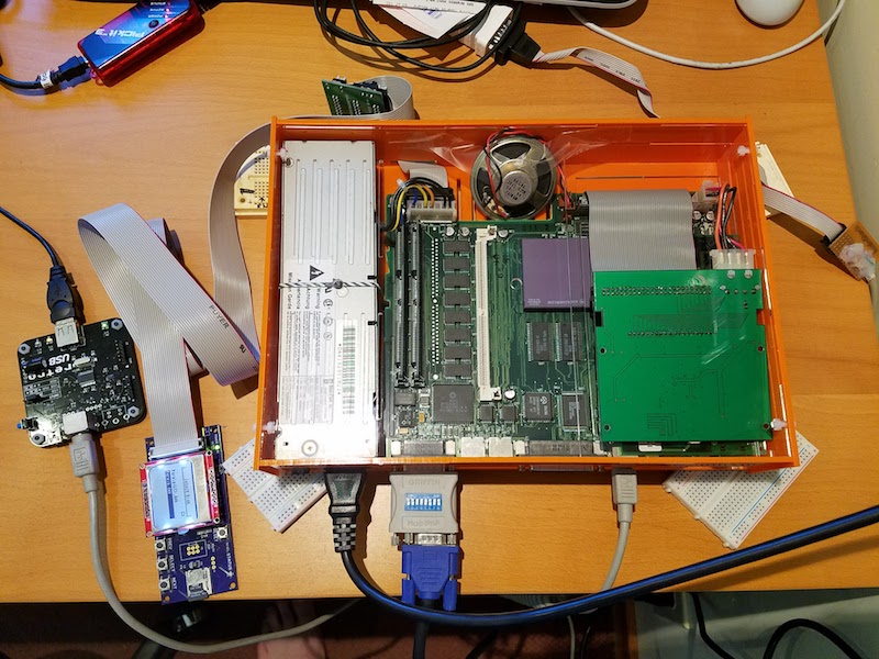
The logic board is screwed into the base piece, and the PSU is strapped down with zip ties. The case is a simple six-sided box, with the addition of a seventh interior piece that I call “the shelf.” This piece separates the rightmost interior region into lower and upper sections. The lower section houses any PDS plug-in card, and the SCSI2SD rests on top of the shelf in the upper section. Because of the way the SCSI cables are oriented, the SCSI2SD is mounted upside-down.
Here are the parts before assembly:
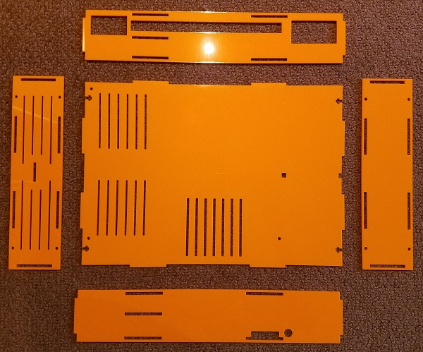
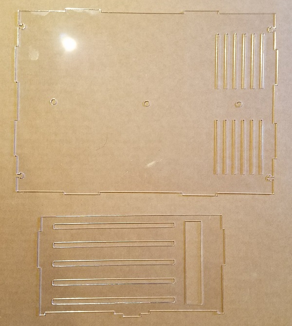
And the final product is shown at the top of this post. It’s an obnoxious shade of orange with a clear top. Who wants beige, anyway?
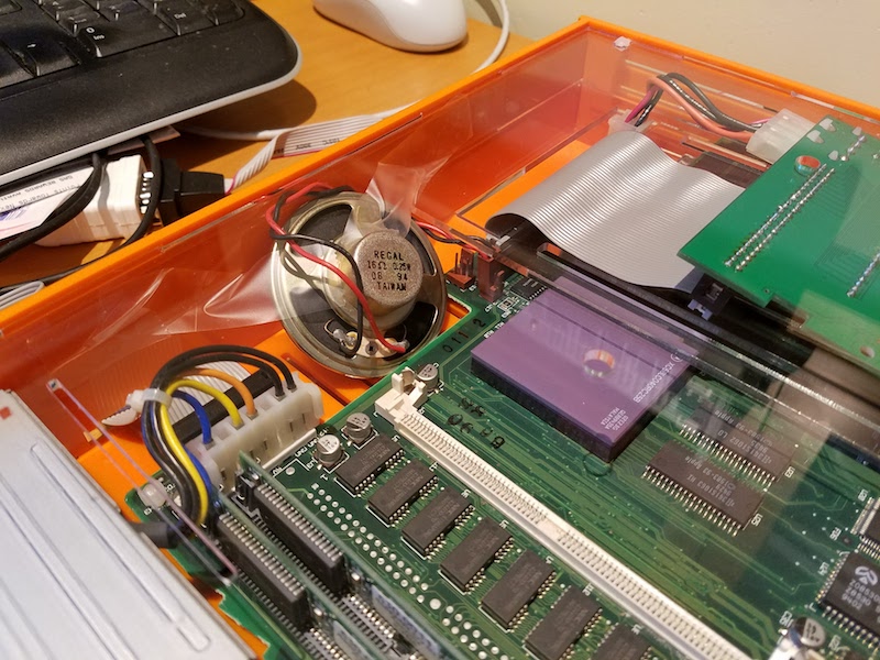
The speaker is taped to the inside of the case to prevent it from moving around, which is ugly. There’s not enough space for it to lie flat, so it’s propped up at a strange angle. I’ll hunt around for a smaller 16 ohm speaker to use in its place.
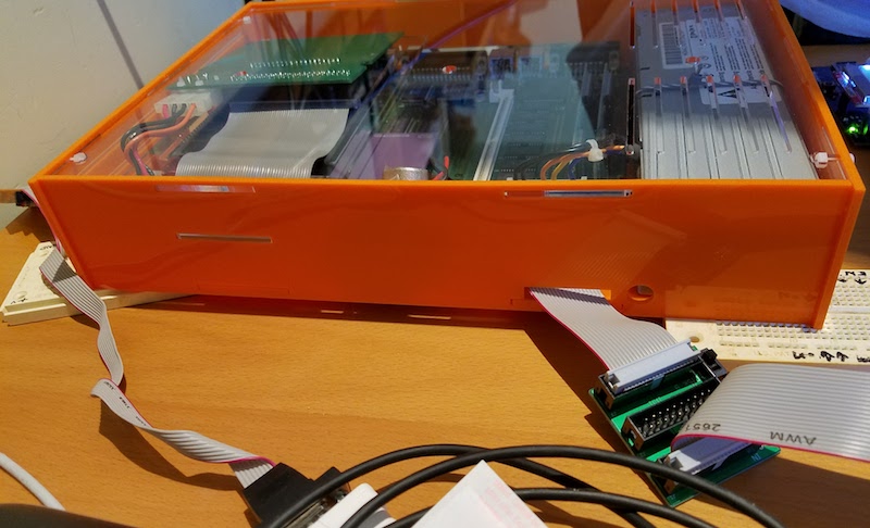
There’s a slot in the front where I’ve run a floppy ribbon cable, so I can hook up a Floppy Emu when needed.
The space above and below the shelf is very cramped, and I probably should have made it larger. Initially I couldn’t get my PDS ethernet card to fit, but after shaving a few millimeters by removing the metal shield from around the ethernet jack, it just barely squeezes in. The SCSI2SD was also a very tight fit. Using a SCSI cable with integrated strain relief, it wouldn’t fit, and I had to substitute a different SCSI cable without strain relief that’s a couple of mm thinner.
The case opening for the PDS card is fine, but without the metal shield, there’s a gap around the ethernet jack. Bonus ventilation! Here’s a photo of that, along with the right side vents:
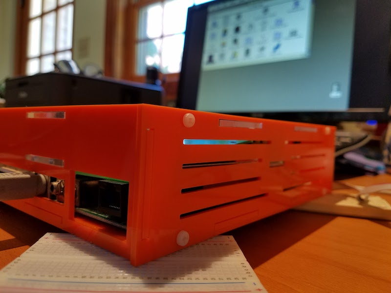
With no fan I thought the computer might overheat, so I was prepared to take some temperature measurements. Stuffed with the guts of a Performa 475, I used an IR thermometer to take some readings at different spots inside the case, and I couldn’t find anything warmer than 112 F / 44 C. I was ready to mount a tiny fan inside, but that doesn’t look necessary now since the passive cooling is adequate.
If anybody wants to build their own, or use this as a starting point for further experiments, take these files. There are two files: one for the bottom and sides, and one for the top and shelf, so you can have the two different sheets made in different colors. Upload the files to ponoko.com, and have each one cut on a P2 sized 3mm thick acrylic of your color choice. You can also use 3mm MDF wood if you want a different look. Along with the case pieces, you’ll need 11 M3x10mm screws with matching nuts. #4-40 size screws probably fit too, but I haven’t tried it. You’ll also want some plastic zip ties to strap down the power supply.
A few things I’d do differently, if I were going to do this again:
- Add about 3mm to the height under the shelf, to fit thicker PDS cards
- Add about 3mm to the height above the shelf, to fit thicker SCSI cables
- Integrate small feet into the side pieces, to elevate the case for better underside airflow
- Have fewer vents around the PSU, and more vents around the CPU and PDS card
- Cut the vent slots into the shape of an Apple logo
- Reposition the floppy cable slot, so it’s better aligned with the logic board’s floppy connector
- Add an opening for a power LED so I can tell when it’s on
Now back to playing with my little orange monster…
Read 6 comments and join the conversation

