Archive for June, 2017
ESP8266, Freeboard.io, Blynk, and IoT
The ESP8266 has exploded in popularity since its introduction a few years ago. With easy to use Arduino-compatible modules like the Wemos D1 Mini, it’s like having an Arduino that’s 5-10x faster, has 128x more memory, and has built-in WiFi, all for the ridiculously cheap price of $4. It’s pretty amazing stuff, really.
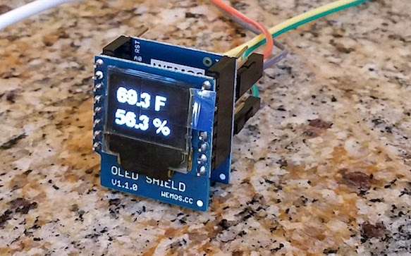
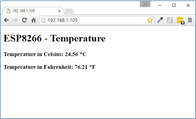
Like everyone else, I began my ESP8266 adventures with a temperature logging application. Using the D1 Mini, an OLED display shield, and an SHT30 temperature/humidity sensor shield, I was able to create a working temperature monitor in about 15 minutes. It shows the current temperature and humidity on the display, and also runs a basic web server for remote viewing of the data. The only hiccup was the heat generated by the ESP8266, which was enough to raise the temperature about 10 degrees F above ambient temperature when the SHT30 shield was plugged directly into the D1 Mini base. Separating the modules with hookup wires solved that problem. The result was something like this:
Logging and Displaying IoT Data
That’s great for a few minutes of work, but how can I make a single page that shows data from many sensors? Or historical data showing the temperature trend over the past 24 hours? Or a more attractive visualization UI than plain text? Or bidirectional control – the ability to switch some equipment at the sensor on/off? This is the realm of IoT data logging and display dashboard solutions, and there are many options.
One approach is to run a local server to do the job, like a Raspberry Pi or an old PC. There are lots of options for software packages you can install on the server, which will log the data and serve up nice-looking pages to visualize it. I didn’t explore this route, because I was too lazy. I also dislike the idea of connecting to a random 192.168.1.8 server address that changes every time my home network reassigns the address through DHCP. I’m sure there’s a way to give it a fixed address and name like “weather-info.local”, but I didn’t look into it.
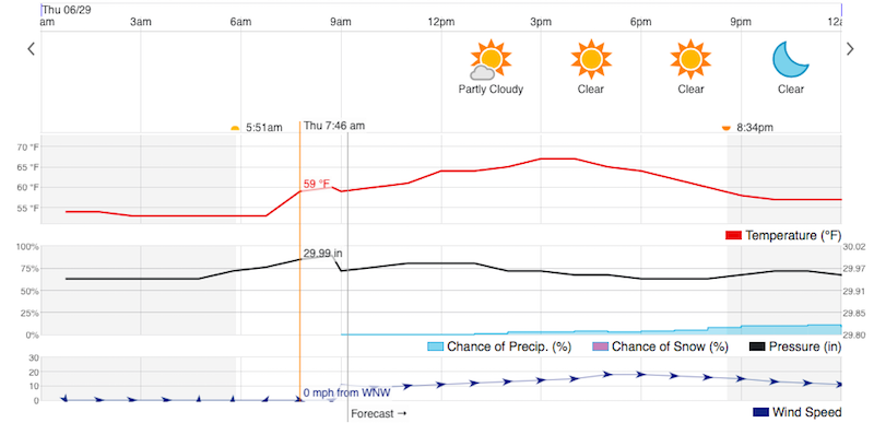
There exist a dizzying number of cloud-based logging and visualization solutions. My ideal solution would would have a nice-looking historical graph of the data, with an adjustable time scale, like the example below from Weather Underground. And of course it would be easy to integrate into my ESP8266 software, and cheap or free to use.
I’ve yet to find any solution that I love. Here’s a quick run-down of the cloud-based options that I investigated.
Dweet.io and Freeboard.io
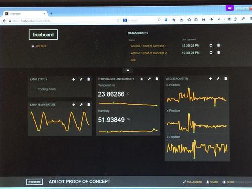
Dweet.io is the data logging service, and Freeboard.io is the dashboard display service. Judging from how frequently they’re mentioned in tutorials and instructables, they’re quite popular. You can also install Freeboard on a local server if you prefer. This setup is for data visualization only, and doesn’t allow for control over the sensor device.
The combination of Dweet plus Freeboard is easy to use, and it looks nice. It would be a great solution except for one shortcoming: there’s no real support for historical data. Freeboard can display sparklines, which are a sort of mini-chart where nothing is labeled and the history is retained in the chart widget itself. Close the web page and re-open it, and your history is gone.
There is an option for a Historical Graph Widget in Freeboard, but it requires upgrading to a paid Dweet Pro account for data storage. That’s only $2/month, but as far as I can tell it means you need to pay before you can try out the historical graph to see if it’s any good. From the screenshots I’ve seen of it, the time axis isn’t labeled and the time scale can’t be modified. It also appears designed to graph a fixed range of historical data, like June 10, rather than a window like past 24 hours.
Freeboard can be extended with plugins, and there are several attractive graphing plugins available. However, all of them appear to function like the sparkline, with the history retained in the graph widget instead of coming from the data source. There may be a solution to do what I need with Freeboard, but I couldn’t find it.
Blynk
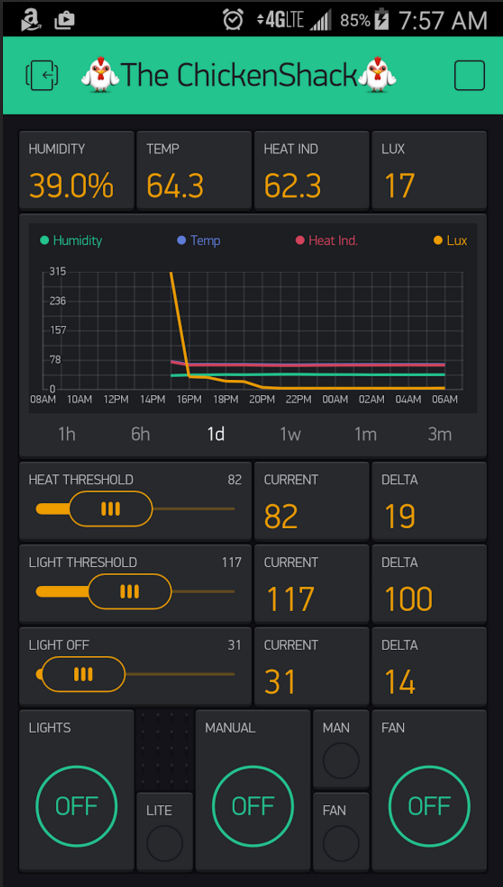
Blynk combines the data logging and dashboard display into a single service. It also provides support for control over devices, in addition to displaying data received from them. Along with Freeboard, it seems to be one of the most popular IoT visualization solutions. It’s easy to use, and attractive.
My biggest complaint about Blynk is that visualization and control is accomplished entirely through mobile apps. There is no facility for viewing your data in a web page – everything happens on your phone or tablet. For some people that might be fine, but I strongly prefer a regular computer with a larger screen and easier control over a complex UI.
The Blynk historical graph widget does almost exactly what I want, with an adjustable timescale showing anywhere from the past 1 hour to past 3 months. But the graph is tiny, and can’t be zoomed or enlarged. It also lacks a cursor feature to display the exact value from some time in the past – you have to eyeball the graph and estimate it. When the whole point of the temperature logger dashboard is to dig into the historical data, it’s disappointing.
Blynk uses an “energy” metaphor that I find to be confusing and silly. Each type of widget added to your dashboard requires a different amount of energy, which must be paid for with an in-app purchase. I would prefer a more straightforward monthly subscription model, with the cost based on things like the number of dashboards and amount of data stored. Charging 2x the energy for a data field display with units vs one without units has no correlation to the developer’s actual costs, and makes me feel like I’m playing Farmville.
Adafruit.IO
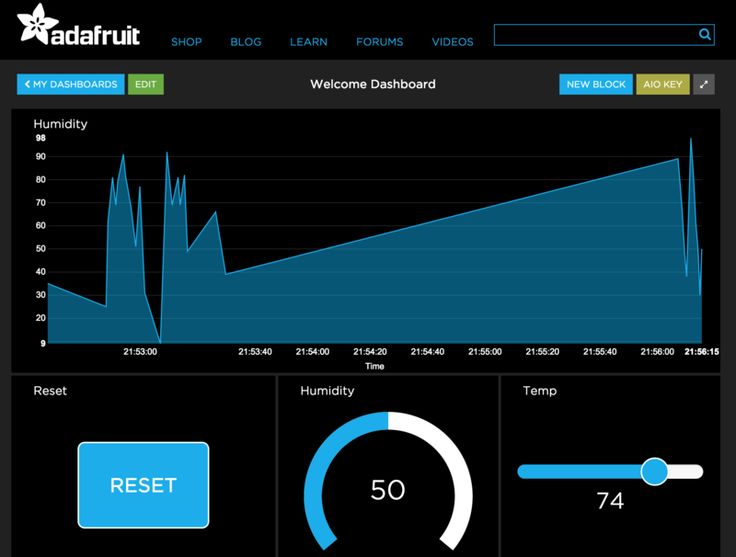
Adafruit.IO is technically still in beta, although it’s open to everyone and has been around for a couple of years. Like Blynk it combines data logging and display, and provides support for both data display and device control. But like Freeboard it’s web-based rather than mobile. Could this be the perfect solution?
From my limited testing it looks promising. The historical graph widget works as expected, and my only gripe is that the time scale must be chosen when the graph is created, so you can make a “past 60 minutes” graph or a “past 24 hours” graph, but not a single graph with an adjustable time scale.
I’m uncertain what the future holds for Adafruit.IO, or whether it’s still being actively developed and maintained. Since the service is completely free, and has been in beta for over two years, it has the feel of a project that was created with great enthusiasm but was left to languish when the developers moved on to something new. Assuming it doesn’t unexpectedly break or get shut down, it looks like a nice solution.
Cayenne
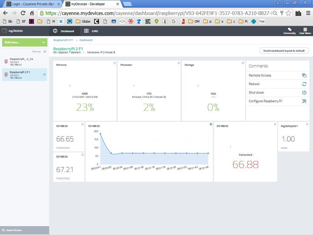
Cayenne is another web-based logger and dashboard like Adafruit.IO. It was recommended in a recent Sparkfun blog post, but I couldn’t find many examples of people using it. Unlike the other services I’ve mentioned, Cayenne appears to be an “app builder” whose goal is to avoid needing to write any code. Instead you use a web GUI to define what type of microcontroller you’re using, what kinds of sensors, and how they’re connected, and then it spits out a complete sketch you can paste into the Arduino IDE. You can probably guess that I’m not too enthusiastic about this approach. Under the hood, the auto-generated code appears to use something very similar to the Blynk API for communicating with the Cayenne server.
I stopped short after reading some Cayenne docs and videos, and never actually tried to integrate it. Maybe I should give it another try, as screenshots of its graphing functions look quite nice. If I can ignore the app builder and auto-generated code, and just use it as a normal API, it might be OK.
A few other alternatives I looked at only very briefly:
Thingspeak – Somehow related to MATLAB, and geared towards doing extensive analysis of the collected data. Might be OK? Most of the references I found were several years old, and I have the impression it’s been eclipsed by some of the newer alternatives.
Emoncms – Looks somewhat promising, but I think it’s only for local server installs and doesn’t have a cloud service.
Losant – Appears geared towards large scale businesses, not makers and home temperature loggers.
Easy IOT – Didn’t make a great first impression – many typos in documentation, complicated setup compared to the other options.
Analog.io – Minimal information on the web page, links to a Hackaday project that hasn’t been updated in a couple of years.
Have you ever used these tools or others like them? I’d love to hear from you – leave a note in the comments.
Read 11 comments and join the conversationMulti-Button Mouse Support

Poor Apple, they never did get on board with having more than a single mouse button. That complicates ADB/USB conversion for USB Wombat. When converting USB to ADB, how should it handle the extra buttons on a USB mouse? What about the mouse wheel? And when converting ADB to USB, how can it generate Windows right-click events from an ADB mouse?
With firmware 0.2.0, I’ve added multi-button mouse support. Here’s how it works:
USB mouse wheel movements send up/down arrow events to the host. This works remarkably well for open file dialogs and document scrolling.
The USB mouse right button can operate in one of two modes:
- Macintosh mode (default): right click sends control + left click event to the host. Works for context menus in Mac OS 8 and later.
- NeXT mode: right click sends a true right click event to the host.
Toggle between Macintosh and NeXT modes by clicking the USB mouse wheel button (button 3).
For ADB-to-USB conversion with firmware 0.2.0, ADB mice and trackballs with more than one button can now use the extra buttons under Windows, OSX, or Linux. Generic multi-button ADB devices using extended Apple mouse protocol should work. I’ve also added vendor specific support for the 4-button Kensington Turbo Mouse 5 model 64210. Other multi-button devices using proprietary protocols may not work. If you’ve got some multi-button ADB mice from MacAlly, Kensington, Logitech, MicoSpeed, Mouse Systems, or others, please give them a try with firmware 0.2.0 and share your results.
Read 4 comments and join the conversationFuture Hardware with Animal Names

Yesterday’s post mentioned some hypothetical marsupial-themed hardware: WiFi Wallaby, Video Platypus, and others. While these were meant as a joke, they got me thinking about what exactly a “Video Platypus” and friends might do, and I’m outlining some possibilities below. These are all tied loosely into vintage Macintosh hardware, although other ideas of interest to the general Arduino/RPi audience would be nice too.
Video Platypus
This might be a way of providing video out for compact Macs like the Plus and SE. I’ve discussed a few potential methods for doing this before. One approach is to directly tap the CRT video and synchronization signals and resample/convert them to a standard format. Another possibility is sniffing the address and data bus to watch for CPU writes to the framebuffer region of main memory, then use that to construct a new video signal.
Video Platypus could also be a converter or upscaler for the Mac II series and later machines. VGA adapters for these machines are inexpensive and easy to find, but VGA itself is a slowly dying standard. It would be nice if I could get a direct HDMI or DVI-D output from my 680X0 or PowerMac. Probably this wouldn’t need to be Mac-specific – it would just be a VGA to HDMI converter with a different physical connector to support the Mac. Something like this must surely exist already?
Disk Kangaroo
An external fileserver would be nice for old Macintosh computers: a device you plug into the computer and that appears as a large local or remote disk. Floppy Emu already serves this purpose when it’s configured in HD20 hard disk mode, but only a small number of Macintosh models support HD20 and have the necessary external floppy connector.
Disk Kangaroo could be something like a Floppy Emu for LocalTalk. Just plug it into the Mac’s LocalTalk port (the printer port), and it would appear as a fileserver. You wouldn’t be able to boot from it the way you can from Floppy Emu, but it would work on virtually every Mac model and system software version. The I/O speed would be about the same as Floppy Emu, I think.
The same idea could be applied to a SCSI disk instead, so the device would appear as a local disk and the computer could boot from it. This would be similar to SCSI2SD, except instead of formatting the whole SD card as a Macintosh disk, the SD card would contain a library of disk images to choose from, just like Floppy Emu. This would make it easier to set up and use for file transfers to and from an internet-connected PC.
Both the SCSI and LocalTalk disks could also use remote storage instead of an SD card. The files could be served from a PC on the same LAN, which would might require some special software on the PC, or the device could potentially do Appletalk-to-Samba translation. Or files could be served directly from a cloud storage account like DropBox.
WiFi Wallaby
Everybody loves the ESP8266 for connecting oddball things to WiFi. What might this do for a vintage computer? Most old Macs are capable of Ethernet networking, although many require an add-in networking card that’s now rare. I’m not sure if it’s easy or even possible to go from that to a wireless network connection.
What might you use this wireless connection for – general web surfing, email, and FTP? Or for connecting to other vintage Apple computers and printers wirelessly with Appletalk?
Maybe this could be like a WiFi version of Farallon PhoneNet. Connect a WiFi Wallaby to each of your computers and printers and they’ll auto-connect and form an Appletalk network. Same idea as the phone cables in PhoneNet, but wireless.
Printer Koala
A clever microcontroller board with the necessary physical connector could emulate an Imagewriter II or other 80’s – 90’s Apple printer. What would be the point of that? Maybe it could act as a print server or translator, enabling the old Macs to use modern printers. The need for printer drivers could make that difficult, though. Or maybe “printing” could perform another function like converting the document to PDF and storing it on an SD card or on a cloud-based server. Or it might implement a print-to-Facebook or print-to-Twitter feature.
Working in the opposite direction could be interesting too: a device that connects to an Imagewriter II or Stylewriter or LaserWriter. The device could put these classic printers on a network so that modern computers could print to them from Windows, OSX, or Linux. There would be a question of printer drivers again, but for relatively simple printers like the Imagewriter that might be doable.
Read 13 comments and join the conversationUSB Wombat: What’s in a Name?

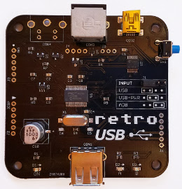
Oops. I belatedly discovered there’s already a Nintendo emulator called Retro USB, which means I need a new name for my USB/ADB input converter. After an exhaustive 5-minute naming process, I’ve decided to continue Floppy Emu’s Australian animal theme and call it USB Wombat. The Australians sure do have plenty of oddball animals to choose from. Coming soon: WiFi Wallaby and Video Platypus?
I’ll update the web site and documentation with the new name soon, but the hardware will keep the Retro USB logo until I exhaust the current supply of boards. The prototype enclosure will need to be updated too. It’s a time-consuming hassle when I’d rather focus on other work, but if a name change is required, it’s surely better to do it sooner rather than later.
Read 9 comments and join the conversationRetro USB Improvements
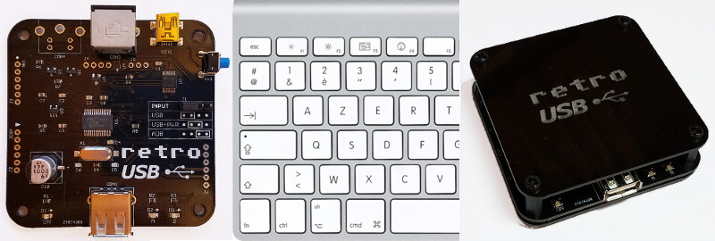
Some good news for Retro USB this week: new hardware, international keyboard improvements, and an enclosure prototype! Everything is maturing nicely, thanks to feedback and assistance from some helpful early adopters. More hardware is available, if you haven’t yet gotten yours. Forward ho!
For anybody who’s newly tuning in, Retro USB is an input converter for USB and ADB keyboards and mice. It works in two directions, connecting modern USB peripherals to a classic ADB-based Macintosh or Apple IIgs computer, or ADB peripherals to a USB-based computer running Windows, OSX, or Linux.
Board Version 1.2
After a slightly bumpy start, I’ve finally perfected the PCB design with version 1.2. This is the first version whose assembly won’t require me to apply manual fix-ups for my design mistakes, so the assembly process can be simpler and faster. It doesn’t make any difference to the final product, but hand-soldering patch wires and extra resistors is tiresome work. I’m very glad to be rid of that job.
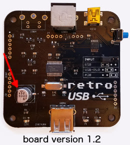
The most significant change in board version 1.2 is the addition of a 1000 uF bulk capacitor for the USB power supply. This enables Retro USB to handle brief spikes in power demand from attached devices, such as the spikes from an Apple A1243 keyboard during its initialization. With this capacitor, there are no problems with “spiky” USB devices like the A1243. The built-in hub on the A1243 works too, and is a convenient spot to attach the mouse.
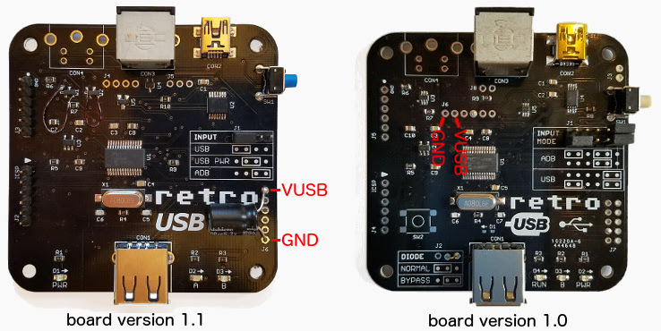
A bulk capacitor can be retrofit to board versions 1.0 and 1.1, if you’re comfortable with some basic soldering. You’ll need a capacitor of 680 uF or more, with a voltage rating of 6.0 volts or more, like this example. Solder the capacitor’s negative terminal to the board’s GND and the capacitor’s positive terminal to the board’s VUSB. See the photos for the board locations to use.
International Keyboards
Firmware version 0.1.15 resolves a few remaining issues for non-US keyboards, and layouts from French to Danish to Estonian and everything in between should now be working, in both USB-to-ADB and ADB-to-USB directions. Please see the International Keyboards section on the main Retro USB page for important details.
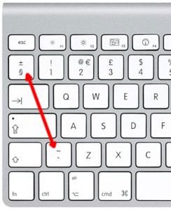
For correct key mapping with non-US keyboards:
- Choose the appropriate keyboard type in your operating system’s keyboard control panel or language preferences
- Set Retro USB to ISO mode (automatic for many keyboard models)
For many countries outside the USA, the USB keyboards designed for Windows PCs have a different layout than Apple keyboards. These PC-type USB keyboards may be used, but key mappings for some symbols will be incorrect where differences exist between the Apple and PC-type layouts. Best results will be obtained with Apple-brand non-US keyboards, or any brand US-layout keyboards.
Other Firmware Improvements
See the change notes included with the latest firmware for a complete list of what’s new. Here are the highlights:
- Right mouse button now works on NeXT computers
- Resolved an issue that prevented ADB keyboard capslock from functioning with macOS Sierra
- Fixed the output from help commands to appear correctly when using a non-QWERTY keyboard
- Fixed missed ADB keyboard events if the mouse is moved while typing
- Fixed device initialization when using multiple cascaded USB hubs
- Added new help command Control-Shift-Capslock-G to show the current keymap type
Enclosure Prototype
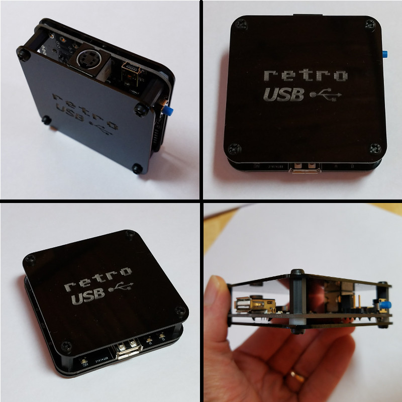
I’m working on a simple enclosure to protect the Retro USB board and add a touch of style. It’s gloss black 1.5 mm acrylic with an engraved logo, and cut to the same shape as the PCB. Add a few spacers and screws, and it makes a nice little package that’s easy to assemble. Initially I’d planned to make a fully-enclosed 6-sided box, but I would have needed to lose the rounded corners, and my experience with the Floppy Emu enclosure has taught me that 6-sided laser-cut enclosures can be awkward to put together. I quite like the appearance and simplicity of this enclosure, and it will probably show up in the store soon.
What’s Next?
Although the start was a little chaotic, Retro USB’s software and hardware now are both looking good, and the device can truly deliver on its plug-and-go promise for ADB and USB conversion. On the software side I’ll be looking at multi-button mouse support soon, so stay tuned for that. For the hardware, most of the effort will go into improving the assembly and testing process, and transitioning away from hand assembly. After that, we will see what else takes shape!
Read 1 comment and join the conversationBuild an Electric Scribble Machine
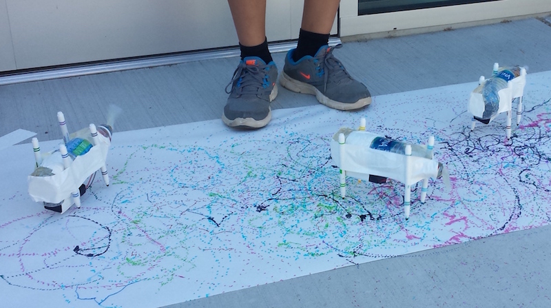
Looking for a creative project for kids to build? The Electric Scribble Machine is an entertaining device that’s easy to build from common parts – great for a scout troop project, school science fair, or just a lazy afternoon at home. For the past several years, as part of our local elementary school’s annual Discovery Day, I’ve led groups of kids ages 7-11 through the construction of a scribble machine. Tomorrow will be my last turn at Discovery Day, so I’m documenting the scribble machine design here for reference.
The basic concept is simple, and is borrowed from an Exploratorium design:
- An off-center weight on an electric motor will cause it to wobble and vibrate
- Mount the wobbly motor to a body made of plastic, cardboard, recycled bottles, or whatever’s available
- Attach colored felt-tip markers to the body to create legs
When the machine is placed on a large sheet of paper, it will wobble and jump around erratically, drawing interesting patterns as it moves.
Step 1 – Motor
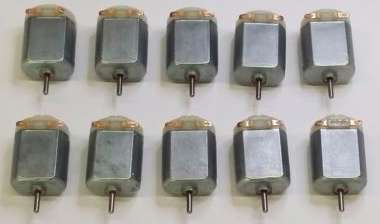
I use cheap DC hobby motors rated for 1.5V to 6.0V. They work fine with just a single AA battery, but are better with 2xAA batteries.
Step 2 – Off-Center Weight
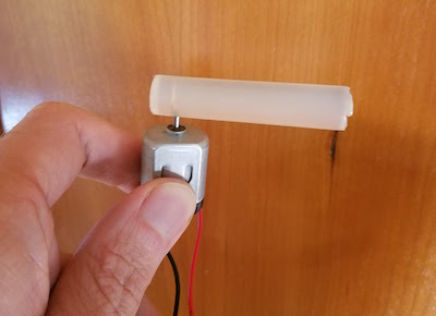
Anything that can be mounted onto the motor’s shaft will work. The more unevenly the weight is distributed, the better. I’ve found that glue sticks for hot glue guns work nicely, and are easy to mount thanks to their texture.
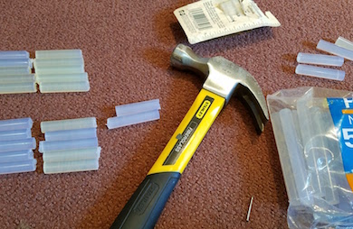
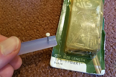
I use generic 4 x 0.44 inch glue sticks, and cut them in half with kitchen scissors to make 2 inch sticks. I hammer in a finishing nail near one end of the stick, then pull out the nail, leaving a small hole behind. The hole makes it easy to press-fit the glue stick onto the motor shaft without any additional tools: just push the shaft into the hole. The rubbery texture of the glue stick holds the shaft tightly, so it won’t easily pull loose.
Step 3 – Battery Holder (optional)
A 2xAA battery holder with an integrated on-off switch helps to create a reliable finished project. In the first years of building scribble machines, I held the motor wires directly to the battery terminals with rubber bands. It worked, but was a constant source of frustration when the wires came loose.
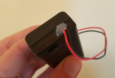
I’ve found that the wires on cheap battery holders are often poor quality, and break easily. Last year, about half of the battery holder / motor units suffered some kind of wire breakage during the day, leading to a lot of unhappy kids and emergency solder repairs. This year, I’ve added a drop of hot glue to the outside of each battery holder at the point where the wires exit. I’m hoping this will serve as a strain relief, and help reduce the number of broken wires.
Step 4 – Soldering (optional)
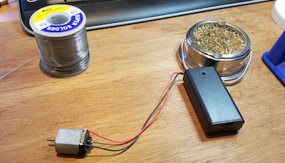
For the most reliable results, the battery holder wires should be soldered to the motor terminals. This is as easy as soldering gets, and it takes only a few seconds. A $15 Radio Shack soldering iron will do the job nicely.
As an alternative to soldering, the battery holder wires could be twisted around the motor terminals with pliers. There’s normally a small hole in the center of each motor terminal, which makes the job fairly easy.
Step 5 – The Body
Here’s an opportunity to get really creative – the body can be made from virtually anything! Try empty water bottles, plastic baskets, DVDs, cardboard, foam board, or whatever else might be handy. In past years I used empty plastic water bottles, sometimes with a few rocks inside to act as ballast. The plastic bottles work fairly well, although they do sometimes get partly crushed by kids who are overzealous in their construction efforts.
This year I’m trying something new: flat cardboard bodies, with holes drilled for the motor and felt-tip markers. It’s definitely possible to create these from old cardboard boxes, but cutting and drilling is time-consuming and tedious when making more than one or two. I took the easy path, and got squares of laser-cut double-thickness cardboard made by a local service. They were only 84 cents each, and the precise cut-outs for the motor and markers make it easy to snap the components into place. I added eight holes for markers, so the kids can experiment with different placements.
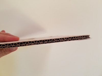
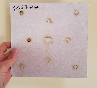
You’re welcome to use my laser-cut design. The Ponoko service will make them for you, if you add the design to your “personal factory” and select a material. Mine were cut from double layer corrugated cardboard, 6.7 mm thickness, 181 x 181 mm size (Ponoko’s standard P1 size).
Step 6 – The Legs
The legs of the Electric Scribbling Machine are generic colored felt-tip markers. Many parents already have dozens of these stuffed into every odd drawer and closet. Washable markers are nice for recovering from accidents, but not required. I used this cheap 30-pack of fine tip markers.
Three legs or four? I’ve tried both, but usually go with four. The design of the scribble machine requires some fine-tuning of stability, and four legs create a more stable base than three. Too much stability isn’t necessarily a good thing, however, since a certain degree of wobbling is required to make a good scribble design. But a high degree of wobbling will quickly lead to wild gyrations, and then the machine will topple over in a sad pile. It takes a few minutes of experimentation with leg lengths and ballast weights to find a happy medium.
Step 7 – Assembly and Use
I normally prepare the battery packs, motors, and glue sticks ahead of time. On the day of the event, the kids combine these with the batteries, body, and legs to assemble a finished machine. It sounds simple, but the assembly process always seems to require a surprisingly large amount of time, usually 30 minutes or more.
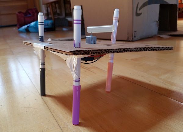
Duct tape, masking tape, rubber bands, or hot glue can be used to mount the motor and battery pack onto the body. These are the heaviest components, so it’s best to place them near the center of the body. I’ve found that most 7 to 11-year-olds don’t have the physical dexterity to work with rubber bands, so duct tape is my preferred adhesive method. After mounting the motor and battery, the legs are attached the same way. The caps on the markers add about 1.5 inches to their length, which needs to be considered while mounting them, otherwise the finished machine will sit too low to the ground when the caps are removed.
After watching the machine scribble random designs for a while, it’s time for some directed experiments.
- What happens if one leg is a different length than the others?
- What’s the effect of moving the legs closer to or further from the body’s center of mass?
- Can you configure the machine to wobble forward in a straight line instead of gyrating randomly? Try racing them.
- Reconfigure the motor to lie on its side, spinning the weight in the vertical plane. How does the machine’s motion change?
- Decorate the bodies with stickers and give them cool names.
Shopping List
Supplies for 30 kids:
30 electric motors $45.00
15 hot glue gun sticks $8.69
30 battery holders $24.36
60 AA batteries $11.87
30 laser-cut cardboard bodies $25.20
100 colored markers $17.44
The total cost is about $132, or $4.42 each.
If you build an Electric Scribble Machine, send me a note and tell me how it went!
Be the first to comment!
