Archive for November, 2011
Implementing Floppy Emu Writes
I’ve yet to implement write support for my SD card Macintosh floppy emulator, but my rough plan was:
- Perform GCR decoding on the fly, and store decoded sectors in RAM
- When the Macintosh steps to the next floppy track, use the delay to flush the sector data to the SD card
- Need to buffer as much as both sides of a 12-sector track, for 24 total sectors, or 12288 bytes
- Use a microcontroller with at least 12K RAM for buffering
Too Slow
For this to work, the microcontroller and the SD card must be fast enough to write 12288 bytes during the track step time. On a real floppy drive, the step time is about 4 ms, but in my tests it can be as long as 12 ms before the Macintosh aborts with an error. 12288 bytes in 12 ms is 8192000 bits/second, so the SPI clock used for SD card communication must be at least 8.192 MHz. On the ATMEGA series, the SPI clock can be at most half the CPU clock speed, so the minimum CPU clock speed would appear to be 16.384 MHz.
But wait, it’s worse than that, because SPI communication isn’t 100% efficient. There’s a delay between each byte, while the microcontroller checks to see if it’s time to send a new byte, and then queues it up. There’s also a delay between each 512 byte block. And if the disk image file being written doesn’t occupy consecutive blocks on the SD card, there will be additional delays between each block, as the SdFatLib code uses the FAT info to locate each block of the file. My rough guesstimate is that actual performance would be 50% to 100% slower than predicted by the SPI clock speed, and that matches the numbers I’ve seen from other people using SdFatLib. To compensate, the CPU clock would need to be 50-100% faster, around 24 MHz to 32 MHz.
A further complication is that the entire 12 ms step window can’t be used for SD writes. Some of that time is needed to update the LCD display, and other housekeeping tasks needed when stepping tracks. To compensate, the CPU clock would need to be still higher.
In short, this approach to writes is simply not going to work on an ATMEGA microcontroller with a maximum clock speed of 20 MHz.
Go Faster
One solution would be to use a different microcontroller that supports higher clock speeds, like an ARM series mcu that was suggested by commenters in the previous post. That would probably work, although I’m reluctant to do it, since it would entail redoing much of the design, learning the details of a new architecture, porting the code to it, and getting programming hardware for the new mcu.
I’m also uncertain how fast the SD card can actually go over SPI, and I haven’t found any definitive answer. The number 25 Mbps appears in a few places, but I think that’s using the multi-bit native SD interface rather than the 1-bit SPI interface. Regardless of the SD card’s capabilities, if I push the SPI clock speed higher, I’ll need to design a circuit board that works well at high clock speeds, which means paying attention to all the board layout details I don’t fully understand and normally ignore. I think I should probably be okay at speeds of 10-20 MHz, but I’m really not sure.
Background Writes
A more complex solution that doesn’t rely on increased clock speeds is to perform SD card writes in the background, while data is being transferred from the Macintosh, instead of trying to squeeze the SD writes into the track step interval. This was suggested by a commenter in an earlier post, and while it would be trickier to implement, it has many advantages.
This method would only require two sector buffers, for 1024 total bytes of RAM. As the Mac sent the data for the first sector to be written, the microcontroller would decode it and store it in RAM buffer 0. After the last byte of the sector’s data was received, the mcu would immediately call an SdFatLib function to write the sector data to the SD card, but it would also install an interrupt handler to be invoked when bytes were received for the next sector. The interrupt handler would store these in RAM buffer 1. The SD write of the first sector would complete well before the last byte of the second sector was received. SdFatLib would then be called to write buffer 1 to the SD card, while the next sector’s data was being stored in buffer 0 by the interrupt routine. In this way, the mcu would always be writing one buffer to the SD card while the interrupt routine filled the other buffer with data for the next sector.
This approach is appealing because it doesn’t require especially fast clock speeds, nor does it require a microcontroller with a large amount of RAM. In fact, it would probably work with the ATMEGA32u4 I’ve been using for breadboard prototyping, which has just 2K of RAM.
In order for this method to work, there must be sufficient time between each “new byte” interrupt to do the following:
- store the processor state and invoke the interrupt handler
- perform GCR decoding on the byte
- store the byte in the RAM buffer
- return to the main program, which is executing an SdFatLib write
- make sufficient progress on the SdFatLib write before the next interrupt so that the write finishes before the last byte of the next sector is received
The interrupt rate is fixed by the Macintosh’s floppy data rate, so the interrupt will be invoked every 16 microseconds. Depending on the ATMEGA’s clock speed, that’s enough for 128 to 320 clock cycles between interrupts. Is that enough to accomplish all of the above? Probably, but it might be a little tight.
Read 8 comments and join the conversationMixing AVRs, Xilinx CPLDs, and JTAG
I’ve been working on optimizing the Floppy Emu design in preparation for making a custom circuit board, and as always I’m faced with a dizzying number of choices and potential trade-offs. The design calls for a Xilinx XC9572XL CPLD along with an Atmel ATMEGA1284P AVR microcontroller, and I’ve belatedly realized that even the simple task of programming these chips will raise some problems.
Programming Connections
For starters, I don’t actually own a Xilinx JTAG programmer, and my Altera JTAG USB Blaster appears to be a single-purpose device, so I’ll have to purchase a new Xilinx programmer. Then I’ll have to cram both a 2×5 JTAG header (for the CPLD) and a 2×3 ISP header (for the AVR) into the board, which seems awkward and redundant. Is there a better way?
The ATMEGA1284P also supports JTAG programming, if you’re willing to give up use of four GPIO pins. I could use a single 2×5 JTAG connector, connect the two chips in a JTAG chain, and use JTAG to program both the microcontroller and the CPLD. But with what programmer? I don’t want to have to purchase a Xilinx JTAG programmer and the Altera AVR JTAG ICE Programmer. There must be a generic JTAG programmer that will work with them both, but I’m uncertain which one, and with what programming software.
Another option is to use the ATMEGA to program the CPLD somehow, by connecting the CPLD’s JTAG pins to GPIO pins on the ATMEGA. Then I’d only need a single 2×3 ISP connector for programming the ATMEGA, and could use the AVR ISP programmer that I already have. But I don’t relish trying to write a JTAG player for the microcontroller, and a brief search to see if something like that already exists didn’t turn up anything.
Voltage Levels and Clock Speeds
Initially I’d planned to run the ATMEGA with an external crystal at 16MHz. Unfortunately, to run at that speed requires a 5V supply, and everything else in the system will be using 3.3V, so level conversion will be required. Although it’s not a horrible problem, level conversion is one more headache that I’d prefer not to deal with. According to my squinting at the graphs in the datasheet, at 3.3V the ATMEGA should safely run at speeds up to 13.3MHz — call it 12MHz to pick a round number on the safe side. Or I could use the internal 8MHz oscillator, and dispense with the external crystal entirely, eliminating yet another part.
But in a system where I’m concerned that write performance may not be fast enough to keep up with the Mac, is it really a good idea to drop the clock speed from 16MHz to 12MHz or 8MHz? For that matter, why not increase the clock speed to the maximum of 20MHz? Or use a different chip like the ATXMEGA192, which has an internal 32MHz oscillator and runs at 3.3V?
The truth is I really don’t know what clock speed will be needed. I’m relatively confident that given a large RAM buffer for track data, reads will work at clock speeds of 8MHz or even lower. Writes are the concern– the Mac will pump out data sector by sector, with no flow control mechanism, so Floppy Emu must either keep up or fail. While the micrcontroller clock speed will clearly be important, the SPI clock speed used to communicate with the SD card is probably even more critical, and that can be varied independently. Furthermore, the reading I’ve done suggests that maximizing SD transfer rates has less to do with increasing the clock speed than with optimizing the transfer code, using multi-sector transfers where possible, and so forth. I’m not sure how well-optimized sdfat lib is in that respect. In the end, while it’s hard to argue against the “faster is better” sentiment, it’s unclear that a higher microcontroller clock speed is necessary or sufficient for making writes work.
Presently I’m leaning towards eliminating the level converter, running the microcontroller at 3.3V, and limiting the clock speed to 12MHz (or 8MHz with the internal oscillator). My reasoning is that the ATMEGA is likely to either be plenty fast enough to support writes, or not even remotely fast enough. Running at 5V with a level converter is only worthwhile if I believe the extra 66% speed bump going from 12MHz to 20MHz will be the difference between being too slow or just fast enough.
Read 6 comments and join the conversationBackwoods Logger, Available Now
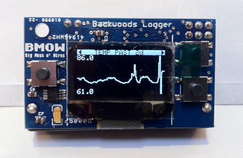
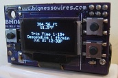
The Backwoods Logger is a programmable graphing altimeter / thermometer, originally developed here at BMOW and now an open hardware project. Interested in the Logger, but don’t want to build it yourself? Assembled Backwoods Logger Mini units, BLsync adapters, and blank Logger Mini PCBs are now available for purchase! Get one for yourself, or as a gift for your favorite outdoorsy nerd. I brought the first prototype with me on the John Muir Trail this past summer, and it was awesome.
What’s it all about, you ask? The Backwoods Logger is a programmable device for measuring and graphing temperature, air pressure, and altitude. It’s designed for hikers, backpackers, climbers, skiers, trail runners, cyclists, kayakers, snowmobilers, horseback riders, and other outdoorsy people interested in environmental data logging over timescales from an hour to a few weeks. The Logger Mini’s features are:
- Graphs of temperature, pressure, and altitude over time
- Three graph time scales: past 2 hours, past 10 hours, past 2.5 days
- Current rate of ascent/descent
- Estimated time of arrival at a user-defined altitude
- Weather forecast
- Station pressure and pressure at sea level
- Snapshot feature – make a permanent record of date, time, altitude, temperature, and pressure at important waypoints
- Current date and time display
- Imperial or metric units option
- Battery voltage indicator
- Sound on/off control
- 3 to 6 month battery life, depending on usage
- Temperature measurements in 0.5 degree steps, from -10F to 117.5F (-23C to 48C)
- Air pressure measurements in 0.01 in-Hg steps, from 5.9 to 36.12 in-Hg (170 to 1250 millibars)
- Altitude (calculated from air pressure) measurements in 2 ft steps, from -1384 ft to 14999 ft (-300 to 4500 meters)
- Download graph data to your PC using the optional BLsync adapter
- 128 x 64 bright white OLED display
- 1.9 x 1.1 x 0.7 inches (48 x 28 x 17 mm) – very small!
- only 0.7 ounces (19g) including AAA battery – very lightweight!
For more details, join the discussion mailing list, check out the user guide, and watch this demonstation video (using the older Logger Classic hardware).
I’ve spent a lot of time getting very familiar with my soldering tools over the past week so that I could bring you these. My hope is that by seeding the community with some pre-assembled Loggers, it will kick-off some firmware hacks and hardware improvements, and take the Backwoods Logger project in exciting new directions.

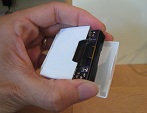
I’ve also built some blsync adapter boards. Blsync is optional and isn’t required for using the Logger, but it’s a handy tool if you want to do detailed analysis of your graph data. Using the blsync adapter along with an FTDI USB-to-serial converter, you can download graph data from the Logger to your PC, and analyze it using Excel or other tools. The adapter plugs into the ISP connector on the rear of the Backwoods Logger, as shown here.

You can also build your own blsync adapter using the schematic on the project web site, if you prefer.
The price for the Logger Mini is $59, and the BLsync adapter board is $6. Blank Logger Mini PCBs are $3. Shipping in the United States by US Postal Service priority mail is a flat $5.20. If you prefer another shipping method or need shipping outside the US, that can be arranged too.
Please email me if you want to purchase a Logger Mini or other parts. I also have one “factory second” Logger Mini, sold for half price at $29, with some dead pixels in the corner of the screen but otherwise working normally. More details available upon request.
Happy logging!


Macintosh Floppy Emu Video
Here’s a brief video of Macintosh Floppy Emu in action, booting a Mac Plus from the emulated floppy, and then reading the floppy using Disk Copy 4.2.
Be the first to comment!
Macintosh Floppy Emu

The Macintosh Floppy Emu works! No, not the flightless Australian bird, but the SD card 800K floppy drive emulator for classic Macintosh computers. I’ve been tinkering with this project for a while now, and wrote about it here several times before. Today I finally got read-only floppy emulation working from an SD card, in a rough approximation of the originally intended design. That makes it possible to download disk images of classic Mac software from the web, copy them to an SD card, and load them onto a Mac Plus or other Macintosh using the Floppy Emu.
Pictured above is the Floppy Emu hardware. Clockwise from the top-left are a custom CPLD board, an Adafruit ATmega32u4 board, and an Adafruit 1.8-inch TFT display with micro-SD card holder underneath. You can just barely see the SD card peeking out under the left edge of the display. In the middle of it all is the big red disk insert button.
The CPLD implements all the timing-sensitive functions and communication with the Mac, but its behavior is simple. The ATmega AVR microcontroller is the brains of the operation. It uses SdFatLib to read 512-byte sectors from a disk image file on the SD card, then passes the bytes one at a time to the CPLD at a speed that mimics a normal external floppy drive. Due to the design of the Macintosh IWM floppy controller, it’s not possible to pass data at a faster bit rate than a real floppy would, although the emulated drive could theoretically be faster overall if its track-to-track step times were faster. In practice I’ve found it difficult to match the performance of a real floppy drive. In its current state the Floppy Emu is actually somewhat slower than the real thing, but still fast enough to keep the floppy controller happy.
Signal Synchronization
Everything was nearly working two days ago, and I had a floppy emulator that worked much of the time, but not 100%. It worked enough so that I could often mount an emulated floppy disk in the Finder, but if I tried to open any of the files on the floppy it would fail with I/O errors. It took an agonizingly long time to isolate the last few bugs, the worst of which proved to be a sort of clock domain synchronization problem when writing to drive registers. The Mac performs a write to the floppy drive’s internal registers by putting the register address and data on the bus, and then asserting the LSTRB signal for a short time. These registers are emulated in the CPLD, but there’s no particular relationship between the timing of the LSTRB signal and the CPLD clock. One of the registers is STEP, and when a zero is written to the register, it moves the drive forward or back one track. My original code looked something like this:
always @(posedge clk) begin
  // was there a positive edge on lstrb?
  if (enable == 1 && reg == REG_STEP && lstrb == 1 && lstrbPrev == 0) begin
    track <= track + 1;
  end
end
The trouble was that the CPLD didn’t always see LSTRB cleanly transition between 0 and 1. Occasionally the CPLD clock would sample LSTRB just as its value was changing, and then funny things would happen. The signal would appear to change from 0 to 1 to 0 to 1 very quickly, causing a double-trigger of the code above, and stepping two tracks when it should only have stepped one. My fix was this:
always @(posedge clk) begin
  // left shift the current lstrb value into a history buffer
  lstrbHistory <= { lstrbHistory[4:0], lstrb };
end

always @(posedge clk) begin
  // was there a positive edge on lstrb?
  if (enable == 1 && reg == REG_STEP && lstrbHistory == 6'b011111) begin
    track <= track + 1;
  end
end
Looking back on it now, the problem seems fairly clear, but it took me ages to discover what was going wrong.
On-the-Fly Sector Retrieval
I’ve examined the designs of a few other floppy disk emulators, and they all use a sensible technique in which an entire track of data is read into a RAM buffer, and then the sectors in that track are continuously “played” from the RAM buffer, over and over until the computer selects a new track. Since everything is in RAM, there are no sector-to-sector delays needed to fetch new data from from the memory card. The only downside to the technique is that it requires a RAM buffer large enough to hold an entire track’s worth of sectors at once. For the Macintosh that’s 6K, plus about 1.5K more for other buffers and SdFatLib. I wanted to use an 8-bit AVR microcontroller, but few of them have 8K+ of RAM, and nothing that I had handy has more than 2K.
To fit the limited memory available, I used an on-the-fly sector retrieval technique instead of the track-at-a-time technique. This technique only requires a single 512 byte buffer, enough for one sector. After the data bytes from a sector have been sent to the Mac, the AVR loads the next sector from the SD card, which takes about 2 milliseconds. On a real floppy the sector-to-sector padding is only about 0.25 milliseconds, but it turns out that the Mac is tolerant of much longer inter-sector delays as long as you keep sending it $FF sync bytes between sectors.
How much slower does this make Floppy Emu data transfers versus a real floppy? The numbers say about 16%. Assuming 10 sectors per track, 752 bytes per sector after GCR encoding, 2 microseconds per bit, then it takes about 122 milliseconds to transfer all the data in a track from a real floppy. Add an extra 2 ms delay between each sector for SD card access, and the total time increases to 142 ms.
In actual use, however, Floppy Emu appears closer to 3x slower than a real floppy disk. Using Disk Copy 4.2, I was able to read an entire 800K floppy in 41 seconds, and an emulated version of that same floppy in 2 minutes 10 seconds. As best as I can tell, the difference is due to some kind of bug that’s triggering the Mac’s retry mechanism, rather than the 20% SD card access overhead. The TFT display shows the emulated active track and side in real-time, so I can see that after every few tracks read during disk copying, the drive seeks down to track 0, then all the way back up to the track where it left off. This looks like some kind of mechanism for coping with unexpected data: the Mac concludes the drive isn’t where it thought it was, so it resyncs by returning to a known location (track 0) and then continuing. It never reports any errors to the OS or the application, though, so I’m not sure how I can determine what’s causing this behavior.
Further Steps
Encode On-the-Fly: The disk image data that’s stored on the SD card is pre-encoded using the GCR tool that I previously wrote for Plus Too. Now that I’ve got a microcontroller that can run plain old C code, it should be easy to do the GCR encoding on-the-fly in the microcontroller instead. That way the disk images on the SD card would be the exact same disk image files used with popular Mac emulators like Mini vMac.
Disk Image Selection: In its current form, there’s no UI for selecting which disk image file to use from the SD card. It simply looks for “floppy.dsk” and that’s it. It would be nice to have a simple UI for navigating the directories on the card, determining which disk image files are in a supported format, and selecting a file to use.
USB: The ATmega32u4 microcontroller that I’m using is USB-capable. Instead of loading the disk image data from an SD card, maybe it could be loaded from an attached PC over USB? I’m not sure it would be fast enough, and maybe it would be more hassle than it’s worth, but it’s an interesting idea.
Writable Floppy Emulation: The current technique is unsuitable for writes. It’s OK to be slower than a real floppy during reads, because Floppy Emu decides when to send the next sector’s worth of data. But for writes there’s no flow control mechanism– the emulator needs to receive, decode, and write to the SD card fast enough to keep up with the Mac, or else it will fail. That’s not possible with the on-the-fly sector method. To support writing to the emulated floppy, it will require an AVR with a large capacity RAM using the track-at-a-time method. Incoming data will be buffered in RAM, and then a full track of data will be written to the SD card during the period while the emulated drive is stepping to the next track.
Read 13 comments and join the conversationExtreme Product Testing
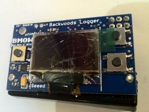
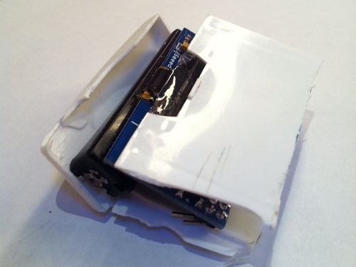
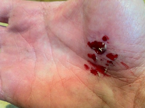
Have you always wondered what would happen to a Backwoods Logger Mini if it were crushed under your own body? No, neither have I, but today I found out anyway. I took out one of the newly-assembled Mini prototypes for a trail run, stored securely in a plastic case in my hip pocket. I wish I could say I was chased down a cliff by a mountain lion or something equally exciting, but the truth is that I tripped on a sidewalk crack before I even made it to the trail. I was running downhill and moving pretty fast, so I went skidding and bumping down the sidewalk with pieces of my hands, knees, elbow, and hip left behind on the concrete. As I hobbled back home, I heard some ominous rattling noises in my pocket. Not good…
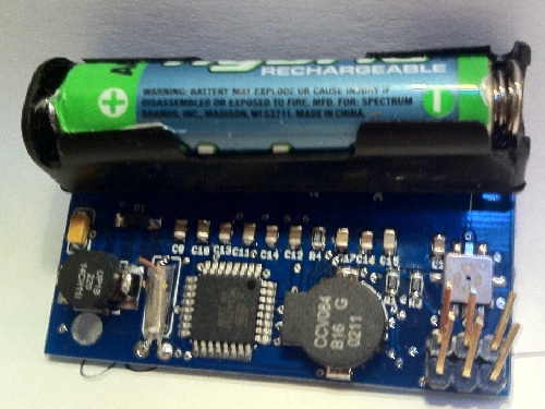
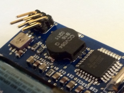
Further examination releaved the sad truth: the Mini took a direct hit when I fell, with all my body weight coming down on it, crushing it between my hip bone and the concrete. The plastic case was completely destroyed and smashed to pieces. The OLED glass was crushed, and part of the ribbon connector ripped off. The NEXT button was flattened and the spring mechanism killed. On the back of the Mini, the header pins were bent nearly 90 degrees over, the negative battery terminal was ripped straight off the board, and a bit of wood got stuck in the RTC crystal.
No, it does not still work.
I’m upset at having lost a prototype, since they take considerable time to assemble and the parts aren’t cheap. At least this makes a more interesting story than losing a prototype to a soldering error!
