Archive for May, 2009
Software-Generated Video
I’ve become interested in software generated video, after reading the book The Black Art of Video Game Console Design by André LaMothe. It’s a unique book, covering everything from atomic theory all the way up to building your own embedded computer system. Unfortunately it’s plagued by a million errors, but I was still fascinated by the idea of direct synthesis of video in software, which is part of the design of the game system discussed in the book.
Most computer systems (including BMOW) have dedicated video display hardware. The CPU writes data to video memory, and at the same time, the display hardware reads data from video memory and synthesizes the actual analog voltages that constitute the video signal for the monitor or TV. In BMOW the display hardware consists of fourteen separate chips, including the video memory itself, character generator, counters for the current row and column, shifter, oscillator, various registers and buffers, and a RAMDAC. It took a long time to design, but it’s pretty powerful.
In contrast, software-generated video creates the final video signal voltages directly from the CPU or microcontroller pins, with no intervening hardware at all except a handful of resistors to form a simple R2R DAC. You’ve got a MCU, some resistors, and that’s all. It generates the video signal in real time, on the fly, and there’s no need for any video memory or frame buffer. Fascinating stuff. The downside is that you need a fast MCU, and your code must be deterministic and per-clock-cycle exactly identical from scanline to scanline. Almost all the processing power is consumed by generating the video, so there’s little left for other logic, and logic code must be interleaved with the video code. I was vaguely aware of this technique before, but never really looked at it deeply because of all these problems with it. At least, that was the case until I saw some of the things the XGameStation from LaMothe’s book can do.
Check out the XGameStation Micro Edition web page. That’s some fairly impressive stuff from a little microcontroller and software-generated video. I decided I wanted to build one of these myself, as a short but interesting detour from work on 3D Graphics Thingy. Most of the XGameStation systems are prebuilt systems, which don’t interest me much, but there’s also the XGameStation Pico Edition that you can put together yourself. Perfect! Except it’s pretty expensive for what you get. I just can’t stomach paying $60 for a kit that contains a $3 microcontroller and a bunch of passive components that I mostly already own anyway. To make matters worse, a $50 SX-Key is also required to program the SX28 microcontroller, bringing the total cost to $110 for a simple little breadboard project.
I did some research, and found that I can get all the parts I need from the $60 Pico Edition kit for under $10 total, except one: the 78.75 MHz clock oscillator. In order to generate color video, you need a high-speed clock that’s an integer multiple of the base NTSC frequency of 3.579545 MHz. Sadly, these just don’t seem to exist anywhere that I’ve found. The only solution appears to be to buy a programmable oscillator, which is what the kit contains, I think. But programmable oscillators with the speed and precision needed are pretty expensive, and only sold in large quantities. Without that oscillator, it’s possible to generate black and white NTSC video only. Of course this still doesn’t change the need for the $50 SX-Key, for which I’ve found no alternative and no used ones for sale. Sigh.
As an alternative, I also looked into making a simple software-generated video system from a PIC24, which is at the heart of another XGameStation design. That’s a little more questionable, since there’s no specific “Pico” design using the PIC24 whose software I could use, but there is a wider selection of tools and software for the PIC series than the SX28. But the same oscillator requirements exist, and while the PicKit2 programmer is a little cheaper than the SX-Key, it’s still not cheap.
At the moment then I’m stuck, and not sure if I should pursue this idea any further. The microcontroller and other parts can be had for just a couple of bucks, so it’s a bit frustrating that the oscillator and programmer requirements are turning this into a $100+ project.
Read 21 comments and join the conversationMore Swag
I’ve been going a little overboard with all the BMOW stuff for the Maker Faire. I’ve spent about $300 on assorted stuff, which is a little crazy considering that this isn’t a profit-making enterprise, and there’s really no good reason to have stickers and posters and books and things, but I can’t stop myself. Help, I think I have a problem!
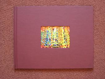
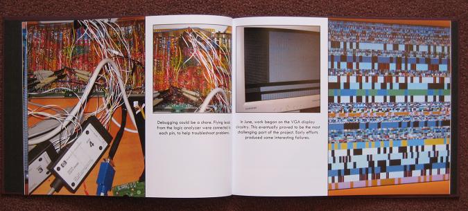
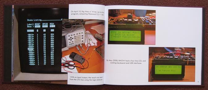
I used Shutterfly to print four large photos of the wiring side of the BMOW main board, which I’ll have around the booth at the Maker Faire. While I was browsing the the Shutterfly site, I also noticed a special they were running: a twenty page 8 x 11 inch hardcover photo book for $23. I couldn’t resist, so I spent a few hours designing a “Making of BMOW” book for people to browse at the booth. It’s a condensed version of the past year and a half of this blog. The book arrived yesterday, and it’s awesome! The front cover has a hole cut in it, framing the photo on the title page, which is a nice touch.

Here are a couple of sample pages from inside the book. It all looks really professional.


I should have stopped there, but I didn’t. Another idea I’ve been mulling for a while is creating a clear cover for the BMOW case. I’m a little worried it might get damaged or spilled upon if I leave the case cover off during the Maker Faire, but with the existing cover in place, it becomes just a boring beige box. I wasn’t really sure how to go about making a custom clear cover though, and never took the idea any further.
Last week it occured to me that a custom clear cover doesn’t really need to be a complete replacement for the metal cover, with full sides, back, guide rails, and so forth. All I really need is a 2D cover that can be mounted to the system board using standoffs, and will protect the board from most hazards from above. That would still leave some small gaps at the sides and edges, but they’d be small enough to not be worrisome. So I took some measurements, spent an hour designing a cover using Corel Draw, and mailed the file off to Pololu, a company that does custom laser cutting of various materials.
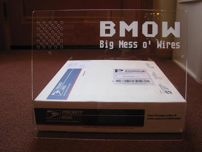
The cover arrived yesterday, and it’s pretty much the coolest thing ever. It’s 1/8″ clear acrylic, with laser cut mounting holes, and a grille for the speaker. The BMOW logo is also etched into the cover, using the laser at a low-power setting so it didn’t burn all the way through.

I’m just blown away that I can spend an hour in a vector drawing program, send the file off into the ether, and three days later get an exact physical part on my doorstep for $29. I’ll definitely be looking for more excuses to custom fabricate parts in the future.
I haven’t yet confirmed that the cover fits, since I need to get the correct size standoffs first. It looks perfect to an eyeball test, though. My vector layout file was based on hand-measurements made with a ruler, so it’s entirely possible that the mounting hole positions are slightly off. I made the hole diameters bigger than needed to allow for some error, and if worse comes to worse, I’ll try drilling out the holes to correct any major mismeasurements.
Read 11 comments and join the conversationFPGA Research
Over the past few days I’ve done a huge amount of reading about both 3D graphics hardware and FPGAs, and I’m starting to get a better picture in my mind of how this 3D Graphics Thingy might be built. My surprising conclusion is that 3DGT may not require any custom hardware at all, but could be entirely implemented using an off-the-shelf FPGA development board. This is either good or bad, depending on your point of view.
Looking back at my earlier “construction notes” posting, I described a vision of 3DGT as a single-board computer with a CPU, FPGA, RAM, ROM, keyboard, USB, and VGA output. That more or less exactly describes an FPGA development board. All the work would then go into creating the HDL for the graphics pipeline, which would be programmed into the FPGA, turning 3DGT into a mostly firmware project. There would still be a few missing hardware pieces when using an FPGA development board, however:
- CPU – I still need a CPU to drive the graphics pipeline, and determine what to draw. Some high-end FPGAs actually have a CPU built-in, but those are out of my price range. My first approach will be to embed a “soft CPU” into the FPGA along with everything else. Xilinx provides a PicoBlaze 8-bit soft CPU that only consumes about 5% of the space in a Spartan 3 FPGA. There’s also the OpenRISC soft CPU from OpenCores.org, if something more powerful is needed. And if a soft CPU doesn’t work out, I can add a real CPU on a daughter card, attached to the development board’s expansion connector.
- VGA – There are lots of development boards with integrated VGA hardware. However, the cheaper boards are all limited to a few bits per color channel. The best I’ve seen is 4:4:4 12-bit color. That will be great for initial testing, but ultimately I’ll need to add a separate 8:8:8 video DAC on a daughter card.
- Joystick, etc – Connecting a gamepad will require a bit of custom hardware, also on a daughter card. Any sound hardware would need to be external to the daughter board too. For initial testing, I can use the built-in keyboard connection.
I like where this is going, although it’s a lot less hardware-oriented than I’d initially expected. Essentially, I can purchase an FPGA development board and get started immediately, using a soft CPU, low bit-depth VGA, and keyboard input. Once the guts of the graphics pipeline are mostly working, I can expand by adding a daughter card with a CPU, video DAC, gamepad connector, etc. For the final version I might create a custom single-board PCB for exactly the hardware I need, and ditch the development board, or just keep the development board + daughter board as the final hardware.
The development boards I’m considering are Xilinx’s Spartan-3E Starter Kit and Spartan-3A Starter Kit. These seem to be the best fit as far as including the parts I need, without a lot of other parts I don’t need, or costing a million dollars. There’s also a wealth of information and tutorials online about how to use these boards, from Xilinx and third parties.
Both boards include the FPGA, 32MB RAM, 16 or 32MB Flash ROM, VGA, USB, PS/2 keyboard input, two serial ports, ethernet, and a two-line LCD. I don’t need the serial ports or Ethernet, of course, but there they are. Both kits come with 50MHz clock oscillators built-in, but I couldn’t find any data on their maximum possible speeds, or the speed grades of the specific FPGAs.
- 3E – The $149 3E is the older board, with a XC3S500E sporting 10476 logic cells, 360K bits of block RAM, and 20 dedicated multipliers. The major drawback is that the VGA output is 1:1:1, allowing for just 8 colors. That would let me work on triangle rasterization, but not color interpolation or texturing. If I ever want to ditch the development board and make a custom PCB, though, the 3E kit is the way to go. The exact same FPGA is available from Sparkfun in a breakout board, as well as from other vendors, or it can also be purchased as a bare IC with leads that I can solder myself.
- 3A – The $189 3A is the newer board, hosting a XC3S700A. The 3A has 13248 logic cells, 360K bits of block RAM, and 20 dedicated multipliers. The larger number of logic cells is nice, but the big advantage of this kit is the 4:4:4 VGA interface, enabling 4096 colors. The drawback is that if I later want to drop the development board and make a custom PCB, it’ll be difficult to do without switching away from the 3A. It’s only available in a leadless BGA package that I can’t hand-solder, and I haven’t found any 3A breakout boards or adapters advertised online.
Along with all this research into the development hardware, I also did some reading about other similar 3D graphics FPGA projects, hoping I might learn from them. Maybe I didn’t dig hard enough, but I didn’t find much, and what I did find were all unfinished projects:
- Manticore – A project started by two students at the University of Alberta in 2002, but never finished. They implemented a basic rasterizer that will be very interesting to examine, as well as a memory controller to arbitrate memory requests and talk to DRAM. They never worked out all the bugs in the rasterizer though, and the design lacks a z-buffer and texture mapping.
- Niklas Knutsson Thesis Project – A 2005 Master’s thesis from Linköping University, Sweden. This is a great description of the task of implementing a 3D graphics pipeline in an FPGA, but the implementation was never finished. He got as far as drawing some basic test patterns, but most of the design time was spent on the CPU and memory controller, so the 3D pipeline wasn’t fully fleshed out. The HDL source and schematics don’t seem to be available online, unfortunately.
- Open Graphics Project – This is an ongoing project to build a fully PC-compatible graphics card, using a pair of FPGAs on a PCI card. Coincidentally, it was featured on the front page of Slashdot just yesterday. The majority of the development so far appears to have centered on the PCI interface, and support for legacy VGA modes. The documentation on the 3D pipeline is fairly skeletal, and it appears that little of it has actually been implemented so far.
I’m surprised there aren’t more projects out there like this, and apparently none that were ever successful. I’m guessing that such projects do exist, and I’ll just have to dig a little deeper to find them.
Read 7 comments and join the conversation
