Archive for 2008
Keyboardin’ Part 3

The keyboard hardware interface works! I’m now a happy key-tapping fool, because with its own keyboard and LCD display, BMOW can operate completely independently from any host PC. The 4×20 LCD is certainly a very cramped workspace, so a Hyperterminal connection over USB from a PC is still the most practical solution for any serious BMOW interaction. But for the sheer cool factor, a stand-alone BMOW with its own I/O beats a USB tether to a Wintel box hands down.
Of course I can’t actually type anything useful with the keyboard interface yet, that would be too easy. You might think that the keyboard sends ASCII bytes to the computer as you type them, similar to a terminal connection, but in fact it’s a totally different interface. Each keypress sends a scan code to the computer, which is normally a single byte but can sometimes be two or three bytes. Then when the key is released, the keyboard sends a “break” scan code, followed by another scan code for the released key, which is usually but not always the same as the keypress scan code. Even the shift key works this way. So to tell if the user typed a capital “A”, you’ve got to keep track of the current state of the shift key by listening for its keypress and key release scan codes, then translate the scan code byte 0x1C to the “a” key, then finally convert that to the character “A” when the shift key state is factored in. I haven’t written any of the key state and scan code conversion software yet, so while it’s true that my hardware interface works, all it does currently is display scan codes.
My original hardware design for the keyboard interface almost worked on the first try. The only problem I ran into was with the clock signal generated by the keyboard, which is used to synchronize the data it sends to the computer. The rise time on the clock signal was mind-numbingly slow: about 1.2 microseconds to go from 0 to 5 volts. Compare that to BMOW’s main system clock, which rises in about 15 nanoseconds. The slow keyboard clock was causing trouble, because the different BMOW chips connected to it sensed a low-to-high clock transition at slightly different voltages, which equated to substantially different transition times due to the slow rise time. My solution was to feed the keyboard clock signal through a Schmitt trigger inverter, which turns a slowly-changing input like this one into a nice clean, quick low-to-high step.
New Instruction Set?
I’m sort of at a crossroads now, with the basic hardware working, and I need to decide what to do next. There’s still some remaining hardware work, of course: the keyboard and real-time clock, but neither of those is essential. Then there are possible hardware extras, like video. And there’s the entire operating system and software library to consider. My eventual goal is to support multiple programs running at once, managed by a multi-tasking OS.
I find myself gravitating towards a rewrite of the BMOW instruction set. Since the machine is microcoded, there’s nothing specifically tying the hardware to the choice and syntax of instructions. The present instruction set is nearly identical to the 6502 instruction set, which seems like a reasonable fit, but I’m getting more and more annoyed with it. I’ve been looking at the 68000 instruction set, and while its hardware assumptions (e.g. 32-bit registers) don’t match BMOW very well, it feels like a good foundation for a cleaner, simpler instruction set.
My main gripes with the current 6502-style instruction set are:
- Every combination of operation and operand is a unique instruction, which feels clunky and difficult to follow. Loading the X register is LDX, storing Y is STY, transferring A to Y is TAY. Compare this with a 68000-style MOVE SRC, DST. So the previous examples would like something like MOVE (A0), X, MOVE Y, (A0), MOVE A, Y.
- Some obvious-seeming instructions are just missing. You can push A on the stack with PHA, but there’s no PHX or PHY. There’s no instruction to add two registers: only to add a register to a value in memory.
- There are no stack-relative addressing modes. Support for the stack pointer in general is pretty minimal. This makes sense for the 6502’s single-byte stack pointer, but BMOW has a full 24-bit pointer for the stack.
- There’s no concept of an address stored in a register. The ability to auto-increment and decrement address registers is similarly hidden from the assembly programmer.
- All the opcodes are three letters. This is a small thing, but it’s annoying and makes the assembly less readable. It’s not like there’s some budget for opcode name lengths.
I’m thinking of rewriting BMOW’s microcode to implement a new instruction set much closer to the 68000’s. To the assembly programmer, BMOW would appear as three 8-bit data registers (the current A, X, and Y) and two 24-bit address registers (the AR and SP, which presently are visible only at the microcode level). The 8-bit T register would remain hidden. I think I still need it as a temporary location for implementing certain instructions in microcode, but if not, I could expose it as a fourth data register.
Exposing the address registers is the most powerful change. Consider a hypothetical program to copy 100 bytes between two memory locations. First the 6502-style:
LDX #99 loop: LDA $4000, X STA $5000, X DEX BPL loopThen the 68000-style program:
MOVE #99, D0 MOVE $4000, A0 MOVE $5000, A1 loop: MOVE (A0)+, (A1)+ SUB #1, D0BGE loop
It may not be obvious, but I could implement the 68000-style instructions to run this program far faster. For instance, that MOVE (A0)+, (A1)+ could be done in 3 clock cycles, compared with 10-12 for the LDA/STA pair, because the address registers are already set up and no address arithmetic is needed. Furthermore, the 68000-style program could be a subroutine in which the actual source and destination addresses are computed at runtime, while the 6502-style program forces the addresses to be known at assembly time, or to use even slower indirect, indexed addressing.
There are some downsides to replacing the instruction set with a new 68000-style one:
- Performance may be worse in some cases with a 68000-style instruction set. In general, such an instruction set would have slightly simpler instructions, and so would require more instructions to accomplish the same work as a 6502 instruction set. For example, the 6502 instruction LDA $4000 would be translated as the two 68000 instructions MOVE $4000, A0 and MOVE (A0), D0.
- The hardware can’t easily support indexed address modes like MOVE 4(A0), D0. That instruction is supposed to load a value from a location in memory 4 bytes beyond where A0 points. That means adding 4 to A0, but there’s no place to store the result of that addition other than back into A0 or A1. So the microcode would need to save and restore the old value of A0 (slow), or make indexed address modes actually change the address register (an unwanted change in semantics), or drop support for that address mode entirely.
- All software and tools would need to be written from scratch. Currently I’m using a modified 6502 assembler, and I can sort of run existing 6502 programs with a little work. But a BMOW-68000 would be different enough from a real 68000 that I’d need to write my own assembler, and couldn’t hope to run existing 68000 programs.
One other option would be to create an instruction set modeled on the 65816, the 16-bit successor to the 6502. It does add stack-relative addressing, as well as some of the obvious-but-missing instructions from the 6502. It still strikes me as rather clunky and non-symmetric, but I should probably take a deeper look at it before jumping to conclusions.
Read 5 comments and join the conversationUSB Action
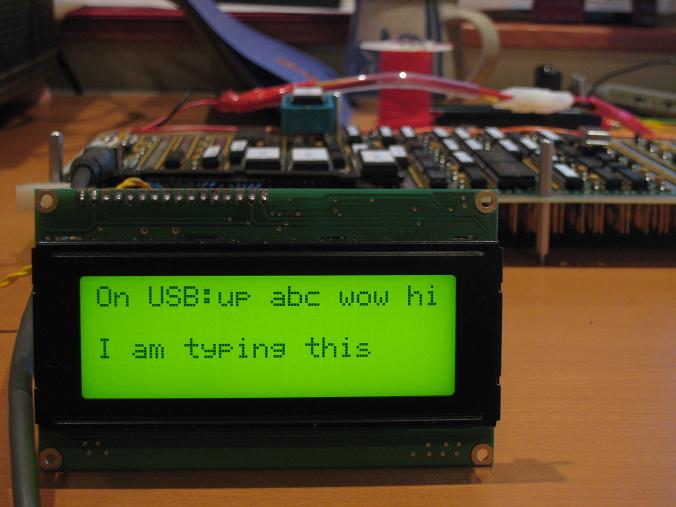
BMOW is now USB-enabled for PC communication, for both reads and writes. Yahoo!

I wrote a simple program to log when the USB interface goes up and down, and to echo all bytes received from the PC to BMOW’s LCD. The program also adds one to each received byte before transmitting it back, so I could prove it was transmitting real data and I wasn’t seeing some local echo. The result was that whatever letter I typed on the PC, the next letter of the alphabet got sent back in reply. Here’s the Windows Hyperterminal session:

The whole exercise went very smoothly, and I didn’t have to do any debugging at all. Once I got the USBMOD4 in place, it all worked on the first attempt you see here.
The only wrinkle was with the USBMOD4 itself. I bought one months ago that was damaged in shipping: some pins were broken off. Futurlec sent me a replacement, but I didn’t open it until yesterday, only to discover it was the wrong part! After scouring the USBMOD4 data sheet, I worked out a modified solution that let me use the damaged module, which was only possible because all but one of the broken pins were ground pins. I ended up needing to desolder a SMD component on the USBMOD4 body, which was ugly, and I was also forced to use the integrated USB jack rather than the external USB jack I’d planned on. But I can live with the little flaws… and hey, now I’ve got USB!
Read 1 comment and join the conversationValidation Test
Remember that validation test suite I wrote last December? Back then, I ran it using a Verilog hardware simulation of BMOW, and it exercised every variant of every machine instruction: adds, jumps, xors, loads, stores, branches taken, branches not taken, branches forward, branches backward, branches across a page boundary, and on and on in mind-numbing variation. Now I have that same test running and passing on the real BMOW hardware! OK, I had to cheat a little and disable the stack-related tests, since I still haven’t wired up the stack pointer register. But the other 95% of the tests run perfectly and the LCD says “pass”. Things are really looking good!
The stack pointer is the next obvious step. I’m a little hesitant to do the wiring, since the last two pieces of hardware that I added each made the machine stop working, and led to frustrating debug sessions. Hopefully this time will go better. Then the core “computing” part of the computer’s hardware will be done, and I can begin on I/O (keyboard, USB) and the real-time clock.
Read 3 comments and join the conversationRAM Test
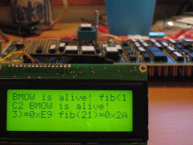
Egads! The RAM works. This thing is starting to look like a real computer now. I wrote an improved version of my fibonacci program that operates on 16-bit values, using 4 bytes of RAM as temporary storage. I then created a super-program by combining the 16-bit RAM-based fibonacci with my earlier 8-bit fibonacci that uses only the A, X, and Y registers, as well as the “BMOW is alive!” program. At bootup, the super-program checks the value in the A register and uses it to choose one of the three demo programs to run. Each demo program writes a new value into A before halting. Since A isn’t cleared when the machine is reset, every time I hit the reset switch it runs the next program in the demo loop. Woohoo, user interactivity! Here’s a photo after running all three:

I’m using the 20×4 LCD now instead of the 16×2 one from the earlier photos. The fibonacci results are written in hexadecimal, since it was easiest for me to generate. The text is a little hard to interpret, because the LCD is mapped as two logical lines, where the first logical line covers the first and third physical lines of the LCD, and the second logical line covers the second and fourth physical lines. It reads “BMOW is alive! fib(13)=0xE9 fib(21)=0x2AC2 BMOW is alive!”
Some system facts:
- Current clock speed is 1MHz. It should be able to go faster ultimately.
- 512 KBytes of RAM, 16 KBytes of ROM.
- Power draw is 8 Watts, implying 1.6A at 5V.
- There are presently 704 connecting wires, so 1408 individual wire wraps.
It’s been a while since I posted any photos of the overall construction progress, so an update is overdue.

Here’s a close-up of the wire-wrap side of the board. Things are getting a little crazy. The photo doesn’t do justice to the fine detail of the dense wiring. Wires are stacked 10 deep in some channels! Big Mess o’ Wires indeed.

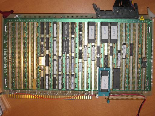
The component side is well-populated now. Eventually the rest of the bottom and right side of the board will be filled. The left side will be available for any possible future expansion, like audio or video.

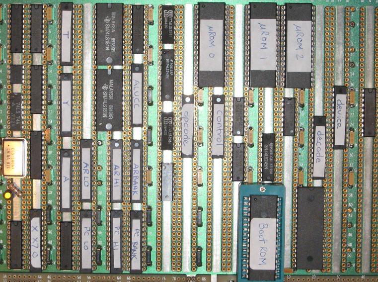
Here you can see the three micro-ROMs at the top, and boot/program ROM below. That’s the newly-installed RAM immediately to the right of the boot ROM. All of the narrow chips with white labels are GALs. The rest of the unmarked chips are various 74LS series logic parts. Since there’s no fan or other moving parts to make an obvious noise, I added the yellow LED below the clock oscillator to remind me when BMOW is on.
Read 2 comments and join the conversationMore Hardware Woes
After my earlier hardware glitches were seemingly resolved, I added the RAM to BMOW, which is the last of the basic hardware components needed. Unfortunately, this created a huge new set of hardware problems that I can only describe as “everything’s broken.” I haven’t even attempted to use the RAM yet, but its mere presence in the system (and the wires connected to it) seems to have caused everything to go haywire, and now the old “BMOW is alive!” program no longer works at all. I haven’t had time to really nail down what’s going wrong yet, but there are so many signals that suddenly seem to intermittently get the wrong values, I feel like my whole house of cards has just collapsed.
Update: A ROM was loose. D’oh! BMOW is alive, again.

