Video Demo
Yarrgh, thar be pixels!
BMOW’s video system still has many minor issues to resolve, but the critical pieces are all working now. I can set up a video mode, poke bytes into video memory, and see pixels on the screen. I can even display digital photos. It’s almost like a real computer!
In a previous entry, I mentioned that I was having a problem losing VSYNC synchronization when reading or writing large amounts of data to video memory. I never did really find an explanation for that, but I did manage to stop it from happening. I think the problem was related to the mix of logic families among the parts in BMOW’s CPU. Most of the video system uses 74HCT series logic, because I had some idea it would be faster and use less power than the 74LS series parts used everywhere else. With the oscilloscope, I observed some crazy ringing that occurred when the 74HCT244 bus drivers turned on to drive the CPU address bus onto the VRAM address lines. I tried replacing the bus drivers with 74LS244s, and the VSYNC problem vanished. Strange, but I was happy to have a solution after having spent too many hours over several days on other failed attempts to solve the problem.
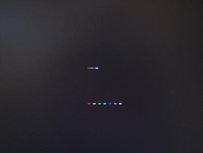
I then turned my attention to actually using the video system. Little by little, I puzzled together what bits I needed to stuff where in order to make something interesting happen. At first it took some time just to find a reliable way to set the video resolution and clear the screen. Did I mention that my design is way too complicated? Eventually I reached the point where I could set pixels at will, and then nothing could stop me. Here’s one of the early pixel tests, which I think is at 128×240 resolution @ 256 colors, showing the eight basic colors of black, red, green, blue, yellow, cyan, magenta, and white. This also demonstrated I could control the palette correctly.
(Click on the images below to see larger versions.)
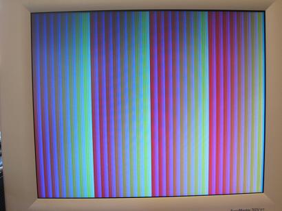
Here’s a color test, similar to the simulated color swatches I showed a few months ago, but this time running on the real hardware.
This random pattern at 256×480 @ 4 colors gives you a feel for the resolution possible at that color depth.
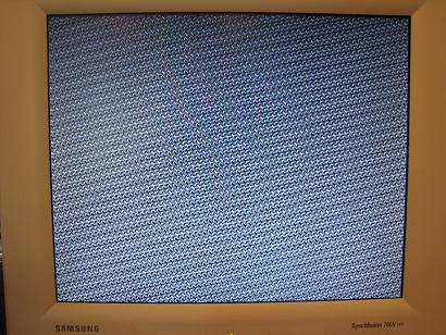
Here’s a similar random pattern in black-and-white at 512×480. It actually feels quite high-resolution, and should make it possible to create some very detailed (if colorless) images.
Random noise at 128×100 @ 256 colors, one of the comparatively few combinations of video settings that allow for nearly-square pixels.
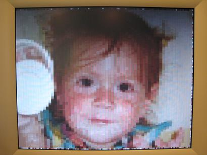
This was my first test of importing a digitized image, in this case a photo of my daughter smeared with yogurt. The resolution of this image is actually limited by the size of my boot ROM, and not the video system. I only had 8K free in the ROM to store an image, which limited me to an image at 64×100 @ 256 colors. The video system supports up to 128×200 @ 256 colors, I just need to find a way to get the image data in there.
Eventually I went so far as to create a BMOW screensaver, with the 64×100 image of Becky bouncing around the 128×200 screen.
It looks decent, but it’s S-L-O-W. There are a couple of reasons for the slowness. The memcopy code I wrote to blit the image into video memory is pretty inefficient. With some care, and perhaps with some new instructions added to BMOW’s instruction set to help optimize memory copies, I think I could speed this up at least 2x, possibly as much as 10x.
The second reason for the slowness is more interesting. The screen saver waits for the vertical blank period at the end of each video frame before the CPU tries to alter video memory. So most of the time when the video subsystem is scanning memory and spitting out the image to the monitor, the CPU is idle, waiting. During the brief VBLANK period, if updates a few pixels, and then goes back to waiting when the next frame begins. This effectively cuts the video memory bandwidth to about 10% of what it would be otherwise, but it avoids contention from video memory between the CPU and video subsystem.
Here’s what the same screensaver looks like with VBLANK synchronization disabled. You can see that it animates much faster when the CPU isn’t waiting all the time, but it generates noise in the video image whenever the CPU makes a video memory access. The result looks pretty terrible.
I posted my “hello world” video test entry on June 24. That was a stand-alone test circuit using just five chips to create a low-resolution, fixed image. I honestly didn’t think it would take anywhere near this long to deliver on that proof of concept and get BMOW video working, but in retrospect there were quite a few challenges beyond simply getting something to appear on the monitor. The finished system interfaces with the BMOW CPU so the image can be updated on the fly, supports palletized color and dozens of different video resolutions/depths, and also boasts a character generator mode (not quite finished). I’m pretty happy with that set of features.
Read 11 comments and join the conversation11 Comments so far
Leave a reply. For customer support issues, please use the Customer Support link instead of writing comments.


Congratulations! I’ve just started designing my own homebuilt computer and this is a combination of both inspiration and aspiration to make something as fantastic as this.
Excellent! On the second video, is it possible you might just have some pins that are open, not tied to ground? I’m sure there’s some way to clean up that noise a bit. Looked like a nice refresh rate on it if you don’t look at the noise. Either way, pretty impressive!
Thanks Jack. Do you have more details on your project somewhere?
Brandon, the interference in the second video is the result of an intentional design limitation. The video RAM is a standard RAM, and not dual-ported or anything fancy, so it can only do one thing at a time. When the CPU reads or writes from the video memory, it means the video display circuit can’t. Whatever data the CPU was reading or writing ends up getting displayed instead of the pixel at the video circuitry’s current screen refresh position. To avoid this interference, the CPU needs to limit its video memory access to only happen during the vblank part of the frame when nothing’s being drawn to the screen. I chose to live with that limitation, rather than try to design some more complicated arbitration or queueing system for the video memory.
whoah !
So if i understand correctly, using a second video ram chip, and flipping between them just before Vsync could solve your artefacts problem (but would need a much more complex circuit ) ?
( Unless you have enough RAM to use as a buffer before changing video ram, but i guess that transfer speed isn’t high enough for that )
Two video RAMs would work, yes, but it would also need two address busses and two data busses for the video RAMs in order for them to be completely independent. It would also require the CPU to do all its drawing twice: once to the first video RAM, then wait one frame, then once to the second video RAM, since there’s nothing that would automatically copy one to the other.
Using two different regions of the same video RAM wouldn’t solve the problem. It’s not that the CPU is accessing the same video RAM address as the display circuit, but that the CPU is making *any* video RAM access at all. That preempts the values on the address and data busses.
I think “real” video systems either use dual port memory, or some kind of queueing system for CPU accesses, or a round-robin access arbitrations between CPU and display. At least one vintage system (TRS-80) used the same solution I did: ignoring the hardware problem entirely, and requiring VBLANK synchronization in software.
Currently I’m still designing it so haven’t put any information up about it. I’m going on the theory that instead of making each instruction take as few cycles as possible you make instructions take as many cycles as is necessary but make each cycle as short as possible. Thus taking away any problems with one particular instruction requiring more time in the cycle than exists and therefore allowing it to be clocked at a higher rate.
I made some optimizations to the inner-most loop of my image copy routine, partially unrolling the loop, and making more effective use of indexed addressing mode. This lowered the time per pixel from 54 clock cycles down to 12, so it now animates 4.5x faster than shown in the video. By adding a new microinstruction specifically for acceleration memory copies, I think I could get that down to about 5 clocks per pixel.
I’m not going to push it any further right now, though. For one thing, the problem with loss of VSYNC synchronization returned sporadically when I tried the optimized loop without limiting drawing to the VBLANK period. Second, I never intended to pursue high-speed full-screen video anyway. My primary goals are to generate a good-looking fixed image, and to be able to change that image quickly enough for scrolling or image cycling. I’m moving on now to text character generation, the last remaining piece of the video puzzle.
Jack, shoot me an email if I can be any help as you fill out your design.
digital image, so that’s a jpg or any other format except .bmp?
How?
and How the .bmp Hello world works?
If this would be too big to explain in a comment, shoot me an email to makerimagesgames@gmail.com
The software I wrote copies the pixels one at a time from a BMP file to the video memory. I chose BMP because it’s an uncompressed format, and supports the color depth of the hardware. JPG wouldn’t work because it’s a lossy format, but something like GIF probably would.
Cool, expect a question filled email shortly.