

Construction
After ages of procrastination, I’m finally making some slow but measurable progress towards turning my paper design into reality, and actually building this crazy machine. Wire wrapping seems impossibly slow and tedious compared with working on a protoboard. Just creating a wiring list from the schematics is taking me lots of time, and the task of physically wrapping the wires isn’t speedy either. Nevertheless, I finished the entire clock generation system and verified that it works. I’d estimate that I’m about 5 or 10 percent done with the whole job, which doesn’t sound like much, but is still far better than zero!
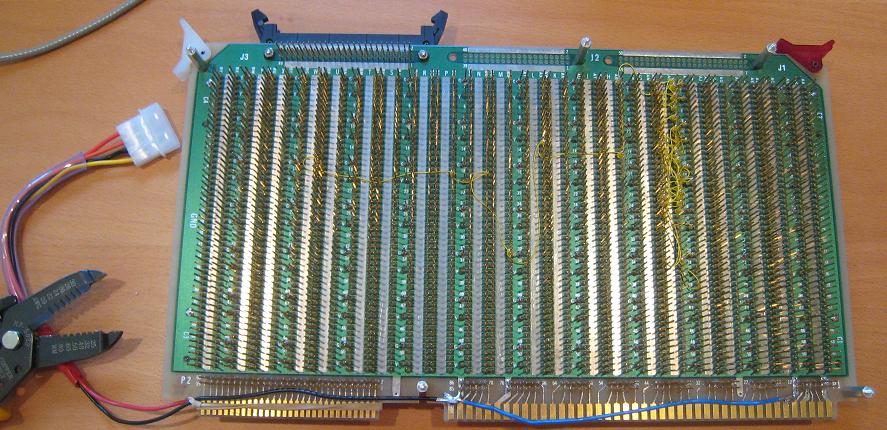
It was tough to get a clear photo of the wire side of the board, but here you can see what’s going on. The tangle of yellow wires near the right side is the clock generation system, and the yellow wires snaking off towards the left carry the clock signals for the chips. Eventually the entire board to the left of the clock generation system will be filled with wires, so that gives you an idea of how far I still have to go.
Hanging off the left, you can also see the 4-pin molex connector I attached for the power supply. It’s a standard PC power supply connector, like the type you’d use for a hard drive or case fan, so eventually I’ll be able to drop the board into the PC case I bought. I’ve also rigged up an adapter (not shown) that lets me connect the board to a simpler wall-wart power supply.
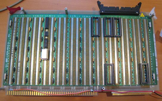
Here’s the component side of the board. You can see I’ve soldered in capacitors between power and ground nearly everywhere. The power filter caps are all those little vertical black or yellow boxes. You can also see the components of the clock generation system in column F, and the ROM sockets.

Here’s a shot of the clock signal at the end of that wire daisy-chain. Looks pretty clean. Of course there are no components connected to the clock yet that might screw up the signal, and this is also with a 500kHz clock rather than the intended 3MHz clock. Hopefully the clock signal won’t degenerate into unrecognizable noise by the time everything’s finished.
I wonder if it would be better to use CMOS components to generate the clock signal instead of TTL, since they’d drive all the way to 5 volts, and so would presumably help with any future noise problems. You can see here that the clock signal only goes to about 4 volts during the high portion.
Read 2 comments and join the conversation2 Comments so far
Leave a reply. For customer support issues, please use the Customer Support link instead of writing comments.
I just bought a similar wire wrap board and I am wondering how to solder my filter caps. Did you apply solder on the posts side (which seems a little difficult considering how little space there is to reach the pad with soldering iron) or the component side, or both? I’d appreciate if you could give me a hint 😉
Good question. I soldered the caps on the component side.