The Mother of All USB Wombat Firmware Updates

For three years, the ADB-USB Wombat firmware sat quietly at version 0.3.9. Everything worked well for most people, most of the time, but the key word in that sentence is “most”. My customer support inbox had many stories describing specific models of keyboards that didn’t type, mice that didn’t move, and KVMs that didn’t cooperate. Too many of those stories ended with an unsatisfying “sorry, that device isn’t compatible.” Most of it seemed to be due to limitations of Microchip’s USB stack code, which I didn’t write and don’t understand well.
This fall, with the help of fancy new AI coding tools, I decided to work through that whole list of issues. Between late September and early October, the firmware went through eleven releases, from 0.3.11 to 3.21. Most of them never received any public announcement or release, so everything in 0.3.11 to 3.21 is effectively one giant update. If you have a Wombat, it’s time to update your firmware!
About the version numbers: Yes, it jumped from 0.3.16 to 3.17. I decided to ditch the leading zero, which served no practical purpose.
Greatly Improved USB Device Compatibility
This was the biggest problem, and it had many causes. The first one was a basic byte/word size discrepancy in the USB stack code. When the Wombat fetched a USB device’s HID report descriptor, the code stored the length of the descriptor in an 8-bit variable. Later it checked that value against the expected length, a 16-bit variable. Any descriptor longer than 255 bytes got its length truncated, the length check failed, and device enumeration silently stopped. No keyboard, no mouse, nothing. Simple USB devices have small descriptors, but anything with complex features or lots of buttons can easily exceed 255 bytes. The Logitech Bolt receiver’s touchpad interface alone has a 429-byte descriptor. After fixing this bug, a huge number of devices that had never worked with the Wombat suddenly did.
To fix more compatibility bugs, I realized that my biggest limitation was testing. I could go broke buying hundreds of keyboards and mice and plugging them into the Wombat to see how they were handled. Then I realized that compatibility issues were almost always related to the USB report descriptor, and if I had the descriptor, I could “virtually” test a device against the Wombat without having a physical sample. So I put together a corpus of descriptors from about 200 devices, common ones and weird ones, harvested from forums and bug trackers all over the web. I created a simulator to test how the Wombat handled enumerating and processing sample reports from each device. This proved to be super useful and revealed all sorts of additional Wombat issues.
One big issue uncovered by the corpus testing was keyboards that report their keys as a bitmap instead of as a traditional array of pressed keys. This is common on gaming keyboards that support N-key rollover. The old firmware decoded those bitmaps as if they were key arrays, with entertaining results: on one keyboard tested, pressing the space bar consistently typed the letter “m”. Bitmap keyboards are now fully supported, including keyboards that send both formats on the same interface.
Then there were keyboards running QMK, VIA, Keychron, and Keyboardio firmware, which need to be explicitly asked to switch to the simpler “boot protocol” mode, gaming keyboards that split their keys across several separate USB interfaces (Logitech G810 and some Razer models), gaming mice and KVM switches whose buttons and scroll wheels were ignored by the Wombat, devices that combine a keyboard and mouse in one, and the Apple Magic Keyboard, which misbehaved after pressing Caps Lock because of a bug in how the Wombat sent keyboard LED updates.
Multiple Simultaneous Keyboards and Mice
A notable limitation of the old firmware was that it managed exactly one keyboard and one mouse. If you plugged in more, all but one of them would be ignored, and it wasn’t easy to predict which one would actually work. That caused a lot of confusion, especially because some gaming mice also pretend to be keyboards for their macro buttons, and some keyboards also pretend to be mice. This meant that a real keyboard could end up being ignored because the Wombat was managing the mouse’s macro button keyboard instead.
Now every attached USB keyboard and mouse works at the same time. Keys from all keyboards are combined, mouse movements are added together, and buttons from all mice are merged. It all just works.
To accomplish this, it required more than just code changes to poll additional USB devices and combine their reports. The PIC microcontroller struggled to manage polling and processing of up to 8 USB devices at once while also responding to ADB commands fast enough to meet the timing requirements. I created a special measurement build of the Wombat firmware to capture timing and profiling data, testing it on an Apple IIgs and all of my Macs to find the most challenging environment. The most demanding was the Mac IIci, which fires about 244 ADB commands per second in bursts during startup, with only about 500 microseconds between them. After optimizing the code and carefully reviewing interrupt priorities, the Wombat is now able to handle the heavier USB load while simultaneously processing high-frequency ADB commands, no matter how many devices are attached.
In ADB-to-USB mode, the Wombat now supports up to two ADB keyboards and two ADB mice at the same time, like an Apple Extended Keyboard plus a separate numeric keypad, or a keyboard, a trackball, and a mouse in one daisy chain. ADB devices can also now be plugged in and unplugged while the Wombat is running.
A Real Preferences Menu
The Wombat has no display screen and no buttons except a power key, so how do you configure its settings? Previously the answer was a collection of ugly tricks. Depending on the setting, you might short-click or long-click the mouse wheel, press a magic key combination, or change an option that was incongruously included in the key mapping table. Nobody remembered any of these methods, including me. Only one of these settings was actually preserved when power was turned off, so the rest had to be reconfigured every time.
Now the Wombat has a real preferences menu! Open a text editor or go to the BASIC prompt, press Control-Shift-Capslock-P, and the Wombat “types” a menu into your document:
BMOW Wombat ver 3.21 preferences 1 Keyboard layout is US 2 Mouse speed is 3 of 6 3 Right button is CTRL LEFT CLICK 4 Scroll wheel arrow keys are ON 0 Restore defaults 1234 change, RETURN save, ESC cancel
Press a number key to change a setting. Settings are saved in the Wombat’s flash memory, and survive power-off and firmware updates.
To correctly support this method of virtual typing for menus, the Apple IIgs needed some special love. In GS/OS, the IIgs couldn’t keep up with the speed of the Wombat’s virtual typing. Longer messages apparently overflowed a keyboard buffer in the OS and came out garbled. I didn’t want to slow down the text output for everybody, though, so I developed a way to fingerprint the host computer and detect when it’s a IIgs running GS/OS, based upon the rate of ADB commands received and the mix of commands. That enabled me to slow down the text for GS/OS only.
At the IIgs BASIC prompt, every line of menu text ended in a Return keypress, so BASIC tried to interpret it as a code statement and replied with ?SYNTAX ERROR to each line. That was super annoying, so I developed another fingerprinting technique to detect when the host computer is a IIgs running BASIC. When in BASIC, the Wombat now ends each line of text with Control-X instead of Return, which cancels the line instead of running it.
No Stone Left Unturned
Beyond those three big changes, there was a long list of other fixes and improvements:
- Stuck and lost keys – Several bugs that caused keys to get stuck down, go missing, or arrive in the wrong order are fixed, in both directions.
- Caps Lock – At least half a dozen separate bugs caused the Wombat, the keyboard, and the computer to disagree about whether Caps Lock was on. Caps Lock is now in sync everywhere, including the latching Caps Lock key on Apple Extended Keyboards.
- Startup key combinations – Combinations held down during startup or reset now work reliably: Control-Apple-Reset and the self-test on the Apple IIgs, Command-Option-P-R to reset a Mac’s PRAM, Command-Option-O-F for Open Firmware, and others.
- Screensavers and sleep – In ADB-to-USB mode on a modern computer, the Wombat no longer prevents the computer from going to sleep or starting its screensaver.
- Boot prompts – The Wombat now works correctly in environments that poll the keyboard but never poll the mouse, like the Linux disk encryption password prompt and some BIOS screens.
- ADB devices – Kensington Turbo Mouse 4.0 and 5.0 trackballs work better, and the right button of MacAlly 2-button mice now works.
- USB hubs – The Wombat supports up to 8 hub ports in total, and older firmware crashed if you exceeded that. It now ignores the extra ports, and the -I help command tells you how many were ignored.
Weird Bugs
A few of the bugs that I found were especially interesting.
The hourly screw-up – A few customers had reported problems that occurred regularly after about an hour of Wombat use. One person even told me that after 30-60 minutes of use, their mouse started typing keys on their Mac. I must admit I didn’t give these reports much weight, and thought it must be a coincidence or caused by something else. Ha ha. The actual cause was the Wombat’s microsecond timer, a 32-bit counter. 2^32 microseconds sounds like a long time, but it’s actually only about 72 minutes. When the counter wrapped around, a time comparison in the firmware went wrong and the Wombat thought the Mac had sent an ADB reset. This reset all the ADB devices and a bunch of related state data, without properly reinitializing it again. Chaos ensued.
Intermittent failures – In one of my tests, the USB keyboard occasionally didn’t work after power-up, but I couldn’t figure out why. After much digging, the cause turned out to be the Microchip USB stack’s internal event queue. It held only four events, and when it was full, it silently threw away new events. Because nobody will ever experience more than four USB events before they can respond to them, right? If an event related to enumerating a newly-attached device was lost, that device got stuck waiting forever. A deeper queue plus a timeout fixed this.
Microchip Tools and Automated Testing
Years back when I originally selected the PIC32 for the Wombat, a BMOW reader warned me against it. Not for any hardware reason, but because he said the Microchip tools made him angry. I can now appreciate why.
Virtually every time I return to Wombat development after an extended break, I find that some Windows update or who-knows-what has caused my PICkit 3 programmer to stop working. Again, and again. This time was no exception. Was it a Windows 11 thing? Java update? A USB driver issue? It didn’t help that Microchip themselves discouraged people from buying the PICkit even when it was an active product, and it’s since been discontinued.
I’d been carefully avoiding updating MPLAB X, the Microchip IDE, because it had been such a pain to get configured the first time. But in an attempt to solve my PICkit woes, I finally bit the bullet and updated my 2017 installation of MPLAB X 3.61 to a shiny new MPLAB X 6.20, the most recent version still with PICkit support. I was pleasantly surprised to discover that I could use the 6.20 GUI and debugging tools, but keep the compiler and toolchain from 3.61, so a painful project reconfiguration wasn’t needed. That mostly resolved my PICkit issues, although I’ve still had some mysterious failure episodes where I needed to unplug everything and plug it in again.
Once I had the PICkit mostly working, and attached a serial cable to read the Wombat’s debug output, it opened up some very cool opportunities for automated testing. My AI coding tool created scripts that would flash a new firmware version to the Wombat, run it, look at the serial log output to collect data on timing and USB events, then apply fixes to the firmware based upon the collected data, compile and flash the new firmware, and try again. It modified, tested, and fixed itself in a repeating dev cycle while I sat there drinking beer and watching it work, nodding my head. Impressive stuff.
Be the first to comment!Thoughts on implementing game controller support for the ADB-USB Wombat

The Wombat is great for adapting USB keyboards and mice to classic ADB Macintoshes, and ADB keyboards and mice to modern USB computers. But what about game controllers? They’re not supported. It’s an often-requested feature, but one that’s not as easy to implement as it might seem. The main problem is that unlike keyboards and mice, there doesn’t exist any uniform standard for communicating with game controllers: neither for ADB nor for USB.
In the past when people have asked about game controller support, it’s not always clear if they’re asking to use USB game controllers via the Wombat on a vintage Mac, or if they’re asking to use classic ADB game controllers like those from Gravis via the Wombat on a modern PC. From reviewing the comments and emails I’ve received, I think interest is roughly evenly split between USB-to-ADB and ADB-to-USB game controller support.
I’m using the term “game controller” here to include both joysticks (typically analog) as well as gamepads (typically a collection of buttons with digital on/off status). The challenges involved in both are similar, but the details differ.
USB-to-ADB Game Controller Implementation
Of the two possible directions for adapting game controller communications, this is probably the easier one: connecting USB game controllers via the Wombat to play classic games on a vintage Macintosh. For the moment, let’s limit our thinking to just gamepads with digital buttons. A simple way to implement basic support might be to program the Wombat to make gamepads appear like a keyboard to the Mac, with a fixed key map. For example the D-pad buttons could send arrow key press events, ABXY could literally type A, B, X and Y, and the Select button, Start, and shoulder buttons would send other keyboard key events.
This may be doable, but there are some difficulties. The main issue is that as far as I understand, there’s no true standard way for USB game controllers to communicate their state to a USB host. Some use DirectInput, some use XInput, some use regular USB HID as if they were a standard keyboard or mouse. The Wombat would probably need to support all of these methods, and somehow determine which one to use. DirectInput and XInput differ from regular USB HID, and supporting those input methods would require developing a new feature for the Wombat firmware.
The other big challenge is that apparently there’s no standard order in which USB game controllers report the state of their buttons. One might report its D-pad as buttons 0 through 3, another as buttons 2-5, another as buttons 6-9. That would seem to prevent the Wombat from using any kind of fixed button-to-key mapping, like automatically treating the D-pad buttons as arrow keys, because it wouldn’t know which are the D-pad buttons.
Maybe the games themselves could be configured in their preference settings to expect directional movement input from a weird key combination like X/1/B/A, but I don’t know if all games are that flexible. Probably some are hard-coded to expect arrow keys for movement and space bar to jump or shoot. Users would also probably be confused or frustrated if the behavior and default button-to-key mapping were different depending on the exact brand of USB gamepad they used, seeing different behavior from nearly identical-looking gamepads.
It would be better to include a configuration / mapping layer somewhere, but where? The Wombat lacks any UI of its own, and isn’t suited to that task. Maybe a text configuration file could be loaded from a USB thumb drive. It seems clunky, though.
The USB gamepad wouldn’t necessarily need to appear as a standard keyboard to the ADB Macintosh. Another option could be to make it appear as if a Gravis gamepad were present. This would also require installing the Gravis control panel on the Mac. Fortunately the Gravis ADB protocols have been documented by Tashtari, so it is technically possible, but I’m not sure it would really solve any problems. If the Wombat doesn’t know whether USB gamepad button 1 is D-pad right or the Start button, then it can’t do a sensible job of emulating a Gravis gamepad, no matter how the Gravis control panel is set up. Ultimately I’m not sure that emulating a Gravis device would provide any clear benefit over emulating a keyboard and/or mouse.
Maybe the situation isn’t as bad as I fear, and in practice USB game controllers are more consistent than I think? I could buy a sample set of the 5 or 10 most common or most popular USB game controllers, and analyze how they work. But that could be expensive and time-consuming.
As for joysticks, I know a lot less about how they work, both on the ADB and USB side. According to one report, typical ADB joysticks behave like a mouse+keyboard to the Macintosh, where the “cursor” snaps back the same distance it traveled in the axis when pressure is no longer applied to the stick, and the buttons get mapped to keyboard buttons. I’d probably need to purchase some ADB joysticks to experiment with, to confirm their behaviors and see if there are differences across models and brands.
ADB-to-USB Game Controller Implementation
I’ve thought much less about this direction. To me, it seems the less compelling of the two. There are real reasons to want USB-to-ADB game controller support: you want to play a classic game on your classic Mac, but classic ADB game controllers are very hard to find. A USB game controller plus the Wombat could then serve as a substitute. The purpose of ADB-to-USB game controller support would be more for nostalgia or for laughs maybe. Yeah you could use your ADB Gravis Mousestick II to play a modern game on your Windows machine, but it’s a little silly when you probably already have a perfectly good USB joystick, or can purchase one for a few dollars.
Putting aside the question of rationale, Gravis protocol support would be a must for ADB-to-USB game controller support. All of the most popular ADB game controllers were made by Gravis, so the Wombat definitely would need to know how to talk to them. Translating the input from the Gravis controller and emulating a USB game controller or joystick might be simpler than the reverse task, because I could probably just choose one of the three common interfaces (DirectInput, XInput, USB HID) instead of needing to support all three. And I wouldn’t need to worry about non-standard button mappings, since I’d only need one mapping, and could just copy the mapping from any popular USB game controller. I think.
As you can see, this is all about as clear as mud, and maybe it gives you more appreciation for why game controllers have remained unsupported by the Wombat. It’s just not a straightforward task, and there’s no obvious “best” solution. I’m sharing my thoughts here and looking for your feedback on all of this. Which direction of game controller emulation would be most valuable to you? How would you imagine it working, exactly? Have I overlooked or misunderstood anything important about the implementation details? Do you have any experience with USB game controllers and how they typically work, how they select between the various communication protocols and so on? If you all can help me sketch out a plan that makes sense here, I’ll try to implement it.
Read 5 comments and join the conversationADB-USB Wombat firmware fix for unrecognized USB keyboards and mice

Mea culpa time here. Since the beginnings of the Wombat there have been reports that certain USB keyboards and mice weren’t recognized by the device. Nothing happened when typing or moving the mouse, and the Wombat’s activity LED didn’t blink. The affected devices were usually fancier keyboards and mice with lots of buttons and features, as opposed to plain vanilla $8 two-button mice and generic 101-key keyboards. I had always chalked this up to some unknown issue in the Microchip USB stack code for handling of peripherals with multiple USB interfaces or a single interface with multiple types of data. It was something in the bowels of that code, which I didn’t write and didn’t understand too well, so I treated it as a regrettable known incompatibility.
Recently a few Wombat customers reported more problems like these related to the Logitech Bolt USB receiver, and I decided to take another look. One helpful customer sent me a dump of the Bolt’s USB HID report descriptor as reported by Linux. I dug through the code with the help of AI, attempting to analyze how the USB stack would handle this report descriptor. It looked hopeless, until…
After wading through thousands of lines of mind-numbing USB goo, I found the smoking gun. Upon completing a USB transfer, the code was storing the number of bytes transferred in an 8-bit local variable and then comparing it to the 16-bit expected transfer size. The result was that any transfer larger than 255 bytes would always fail! Please queue the laugh track and sad trombone sound effects.
What does this have to do with composite USB devices? Nothing, except that composite USB devices have more interfaces with more data to report, resulting in larger report descriptors that are more likely to exceed 255 bytes.
Firmware 0.3.11 was released yesterday to fix this bug. It’s not just something relevant to the Logitech Bolt. If you’ve been using the Wombat in USB-to-ADB mode and encountered certain keyboards or mice that just mysteriously didn’t work with the Wombat, please try the new firmware. There’s a good chance that this will fix it.
Read 4 comments and join the conversationFloppy Emu Hardware Failure Analysis Results

Nobody enjoys troubleshooting non-working hardware, and I’m no exception. Every time I ask a contract manufacturer to assemble a batch of more Floppy Emus, there are always a few that don’t pass QA testing. What happens with those? For several years the accumulating QA failures have been sitting in a pile in the corner of my office, along with a few customer returns, all waiting for the day when I would dedicate time to their investigation. It was a long time coming, but “Failure Analysis Day” finally arrived, or more like Failure Analysis Month, and the results were pretty interesting.
Here’s a breakdown of the unique causes of failure that I identified, and the number of boards affected by each cause.
| Hardware Issue Diagnosis | Count |
| clock crystal / no clock | 26 |
| clock crystal / bad clock | 16 |
| bad CPLD chip | 6 |
| microcontroller not programmed | 5 |
| soldering problems | 5 |
| bad microcontroller chip | 4 |
| broken display header | 1 |
| missing component | 1 |
| cracked PCB | 1 |
| no issue, good board | 1 |
| unknown, couldn’t resolve | 2 |
Clock Crystal
This was a strange failure that required a lot of time to track down initially, but once I learned to recognize the symptoms, I realized that most of my QA failures were due to this problem. I wrote about the clock crystal mysteries in more detail in a separate post last month. The short story is that during my most recent manufacturing batch, my normal supplier of clock crystals was out of stock. The contract manufacturer, with my approval, substituted a different crystal with the same specs. It shouldn’t have affected anything. But somehow it did.
26 of the QA failures appeared to have no functioning clock at all. The board utterly failed to do anything when the microcontroller clock source was changed to the external crystal. A further 16 displayed some level of function, but with erratic behavior or failures at higher clock speeds. Initially I wasn’t sure whether this was due to the newer crystals exposing some defect or fragility in the Floppy Emu design, or whether it was simply caused by defective or damaged crystals. Eventually I came to the opinion that the crystals were damaged by rough handling or overheating during assembly. Replacing the crystals and reprogramming the boards resolved all the issues.
CPLD Chip
The Xilinx CPLD chip on the Floppy Emu is a delicate flower that has long been a source of challenges. Prior to this year’s crystal-gate debacle, the CPLD was the single biggest source of failures that I’d observed. As the chip that’s directly connected to the Floppy Emu’s external interface, it bares the brunt of any static discharge or electrical stress. It’s a 5V-tolerant 3.3V part, but its 5V tolerance has sometimes seemed a bit questionable, at least in the way it’s used here.
Symptoms of a failed or bad CPLD can include disk emulation failures, overheating, or erratic behavior. Usually the device will still be functional and text appears on its display, but the disk features no longer work. In extreme cases the failed CPLD acts as a hard short-circuit from power to ground, and then nothing works. Replacing and reprogramming the CPLD resolved all of the problems with these boards.
Microcontroller not programmed
Amusingly, or depressingly depending on your perspective, the third leading cause of QA failures was that the microcontroller simply wasn’t programmed. Somebody fell asleep at the switch at the contract manufacturer, lost track of what they were doing, put a PCB in the wrong pile, or whatever. A board with an unprogrammed microcontroller will appear completely dead at first glance, but it still responds in the debugger and it only takes a few seconds to flash the chip and get everything working.
Soldering problems
Every component must be electrically bonded to the PCB with solder. Soldering problems can be tough to spot with the naked eye, but usually jump out under magnification, so one of my first troubleshooting steps is usually to look at a problematic board at 10x. I really should get a cool desktop microscope, but for the moment I’m using a cheap 10x jeweler’s loupe which works well enough.
A couple of boards had too much solder in places, resulting in a solder bridge that unintentionally connected two adjacent IC pins. But it was more common to find joints with insufficient solder or poor solder joints, where an IC pin was sort of resting on the PCB pad without actually bonding to it. Fortunately both problems were easy to fix with a soldering iron and a bit of flux.
Bad microcontroller chip
The onboard microcontroller trip is another potential source of failure. In my experience, these microcontrollers are pretty robust, and the only failures I have seen are caused in the field when customers accidentally connect the Floppy Emu cable backwards to their Apple II Disk II controller. This is distressingly easy to do, since the Disk II controller has bare pin connectors instead of a shrouded and keyed header. A backwards connection results in +12 and -12 volts applied to the mcu’s pins, killing it.
Unfortunately the symptoms of a bad microcontroller are nearly identical to the symptoms of a bad clock crystal: a completely unresponsive board, with no debugger activity. I had to review each non-responsive board’s history in order to guess which issue was at fault. In some cases I guessed wrong, and I ended up replacing the microcontroller, and then when that didn’t help, also replacing the clock crystal.
Other
The remaining issues were all one-offs. One board’s display header was physically broken and missing a pin, resulting in a blank display. Another board failed QA because the LED didn’t illuminate, except there was no LED! There was only a blank pad on the PCB. I also encountered a failure due to a PCB that was physically cracked, a long line running down the breadth of the PCB that could only be seen clearly under light from a specific angle. Two more boards defied my efforts to pinpoint the cause of their failures, and after spending too much time on them, I threw them into the scrap bin.
The very last board that I examined turned out to have no problems at all. I tested it extensively and it worked perfectly. This might have failed QA due to something external like a bad power supply or cable, or maybe it was simply miscategorized.
Final results
Of 68 Floppy Emus in the failure analysis heap, I managed to resuscitate 65 of them. That’s a pretty solid percentage! I learned to recognize the symptoms of certain failure causes, so I can address them faster if I see them again. More importantly, the failure analysis learnings (especially about clock crystals) will also help guide me in making design and assembly process changes, so I can reduce the number of future QA failures. Knowledge is power, as they say, and now I have lots of power.
Read 1 comment and join the conversationMactoberfest 2026: Exhibits, Activities & More

Planning for the 2026 edition of Mactoberfest Meetup is well underway. This year’s event will take place on Saturday November 7, 2026 in Belmont California. We’re planning a glorious celebration of all things related to the classic Macintosh, with other connected vintage technology too. Don’t miss it!
The previous Mactoberfest Meetup was a hit, and this year promises to be bigger and better. We’ve got a few new things in store for attendees, including sponsors who’ve donated some cool hardware and tools, a Discord channel for pre- and post-meetup conversations between attendees, and more. Look for further announcements about these very soon.
With two months to go until the big day, there are currently 23 exhibitors registered, with more coming. We expect to welcome between 30-40 total exhibitors and several hundred attendees to this year’s Meetup. The next exhibitor to register could be you! If you have an old Mac, Apple II, or related gear, please do sign up as an exhibitor and share your collection. Your participation is highly encouraged, and Mactoberfest is intended to be a collaborative shared experience created by everyone who’s there.
Here are some highlights of what you can expect to find at Mactoberfest Meetup 2026 (with more still to come):
- A vintage Mac DIY repair station stocked with soldering tools, test equipment, and expert help.
- Exhibit of classic Apple and Macintosh networking equipment, highlighting connectivity across Apple II, 68K Macintosh, PowerPC, and early G3 systems.
- Collection tracing the history of Macintosh input devices, including mice and trackballs.
- Exhibit focused on magnetic storage for Macintosh computers, including internal and external hard disk and floppy disk drives.
- Collection of Clarus the Dogcow memorabilia and collectibles.
- After Dark screen saver exhibit featuring an original iMac running screen saver modules alongside a modern macOS emulator developed specifically for After Dark.
- Collection of unusual Macintosh systems, including a Mystic Color Classic with Apple IIe Card, a Power Mac 4400 prototype, and an Assistive Technology Freestyle.
- Mac-compatible handhelds, peripherals, and a hands-on setup for making lo-fi photo name badges.
- “The Satanicube”: an extensively modified and highly unusual Power Mac G4 Cube previously exhibited at VCF West and VCF SoCal.
- Intel Developer Transition Kit, a prototype computer designed to assist with the transition from PowerPC to Intel processors.
- Collection of Apple Newton handheld personal digital assistants.
- Collection of compact Macintosh systems, including 100-series PowerBooks, PowerBook Duos with docks, iBooks, and a PowerPC Mac Mini.
- Power Macintosh 7600 running non-Mac OS systems including Rhapsody, BeOS, and MkLinux, plus Macintosh IIsi running System 7.6, NetBSD, and Debian.
- Complete Power Computing system with original operating system and period promotional materials.
- Macintosh SE with custom MacEffects green case, Macintosh IIcx with Wombat USB accessories and games, Macintosh IIgs with Floppy Emu, and Power Mac G4 Cube with games.
- Macintosh IIfx with NuCF solid-state storage by zigzagjoe and Macintosh Portrait Display, plus a heavily modified Macintosh SE/30.
- Collection of compact Macintosh systems, including Macintosh 512K, Plus, SE, and/or SE/30.
- Macintosh Plus with custom display and miniature displays featuring After Dark screen saver modules.
- Macintosh SE with Voice Navigator, demonstrating early voice control of the Macintosh graphical interface.
- Macintosh IIci with a Caere OmniScan handheld scanner.
- Quadra 650 with PC DOS Card, PowerBook 2400c, graphite iBook, Macworld magazines, and 1990s Apple advertising.
- Macintosh SE running MacWrite and a connected ImageWriter II printer loaded with paper.
- Macintosh LC system in a custom neon orange case.
- Disassembled Macintosh 128K with exposed logic board, and all chips and ports labelled.
- NeXT computer hardware and software, the precursor to Mac OSX.
- Collection of 1980s and 1990s computer magazines including MacUser, MacWorld, and COMPUTE!
- Original Atari Pong home console from 1975.
For more details and to register for Mactoberfest Meetup, visit mactoberfestmeetup.org. You can also support Mactoberfest by contributing a few dollars to help cover our event costs. The meetup is free to attend, and we’re relying on your generous donations to help us pay for this thing. Thank you!
Be the first to comment!Adventures in Microcontroller Circuit Debugging

How do you go about troubleshooting a misbehaving microcontroller circuit? A few months ago I manufactured a new batch of Floppy Emu disk emulators. A number of them failed QA at the factory, with a set of symptoms that I’d never seen before in all my years of developing this device:
- Most of them simply wouldn’t boot up at all, despite verifying that power was good and the mcu was correctly programmed.
- Some exhibited “haunted” behavior, seemingly jumping to random sections of the mcu program code, outputting messages on the display that made no sense given the context.
- One of them appeared to work in slow motion, with LED blinking and display updates noticeably more sluggish than normal.
This was odd, to say the least. I have a lot of experience with the ATMEGA1284 microcontroller and the Floppy Emu circuitry that surrounds it, and I’ve become an expert at guessing what’s wrong based on the symptoms of misbehaving boards. These were all new and bizarre symptoms to me. Might they arise from different problems, or could they all point to one common underlying issue?
My intuition suggested some kind of systematic assembly problem. My contract manufacturer used a new subcontractor for this batch of Floppy Emu boards, so maybe a silent change to the process caused an unexpected issue? Parts substitution? Bad parts? Counterfeit chips? These QA failures sat in a pile on my desk for months, waiting for answers.
Probing, Poking, and Theorizing
Yesterday I finally decided to concentrate on the “won’t boot” devices, since that seemed like the most tractable problem. I put a few boards in a test harness, and connected power and a hardware debugger. The power supply voltages looked good. No obvious soldering problems were evident, but just to be sure I reflowed the solder on a few boards, without seeing any improvement.
On many of the boards, the hardware debugger could talk to the microcontroller and I was able to confirm the chip was correctly configured and programmed, but the program didn’t seem to actually run. At power-up the boards did… nothing. And with a smaller number of the boards, the debugger could not communicate with or even detect the chip. What could cause these symptoms? I brainstormed:
- Bad power. Seemingly ruled out by my measurements.
- Misprogrammed chips. I confirmed the configuration and reprogrammed several, without improvement.
- Bad chips.
- Chips stuck in reset.
- Clock problems.
- Problems with other circuit components (SD Card, CPLD, etc) causing electrical or program failures.
A batch of bad microcontroller chips seemed like the most likely explanation, so I desoldered the ATMEGA1284 from a board and replaced it with a new one from my stash. But after configuring and programming the chip, the board behaved the same as before, refusing to boot. That seemed to rule out problems with the chips themselves.
In the Floppy Emu program code, when the device first powers up, there’s some communication with the SD Card and the CPLD that happens before anything is drawn on the device display. I suspected that something might be going wrong during those steps, causing the program to freeze or crash and resulting in a blank display. To test this, I modified the program to blink the status LED twenty times as proof of life at the start of main() before doing anything else. Yes, with all the hardware tools at my disposal, I was back to caveman debugging with a blinking LED.
But there was still no joy, no LED blinking, no apparent program activity at all during power up. What the hell? Here I had a good microcontroller with good power, confirmed programmed correctly, in a circuit and board design that’s been in successful use for years. It wouldn’t even blink an LED. Since the blinking should have happened as the very first step of the program, its absence mostly seemed to rule out explanations related to failed interactions with other circuit components like the SD Card. So I focused in on the reset signal and the clock, the only two possibilities that I had left.
Clock Crystal Mysteries
Floppy Emu’s microcontroller uses an external 20 MHz crystal for speed and precision, but it also has an internal built-in 8 MHz oscillator. This particular board was still communicating OK with the hardware debugger, so for grins I tried changing the chip’s fuse configuration to select the internal 8 MHz oscillator as the clock source. Lo and behold, it worked! The device booted up and appeared to run normally, although obviously at only 40 percent of normal speed. I confirmed the same result with a few other boards – when I was able to get debugger communication and change the clock source to the internal oscillator, the board would boot. This wasn’t a fix, since the Floppy Emu won’t actually work correctly with an 8 MHz oscillator, but it was proof of major trouble with the external clock crystal.
If an external crystal isn’t working reliably, the microcontroller won’t have a reliable clock source. It will probably fail to run at all, or else act super glitchy. It will also cause problems with debugger communication. This all sounds a lot like my observed symptoms.

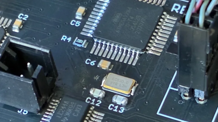
So let’s talk about this crystal oscillator circuit. Like almost all microcontrollers, the ATMEGA series has built in amplifier hardware to drive an external piezo crystal and force it to oscillate, using a circuit that I believe is called a Pierce Oscillator. I should know more about the theory of operation, but I’m mostly ignorant. What I know is that you connect the crystal’s two terminals to two ATMEGA pins using the shortest PCB traces that are practically possible, and add two external capacitors with values in the picofarad range, whose values are determined by a formula, and then everything works.
Investigating a bit further, I observed that all of the problem boards used a different crystal manufacturer than I have used previously. That’s fine, it shouldn’t have been an issue, but it seemed important given the circumstances. Previous editions of the board used this NDK crystal, but these troublesome boards substituted a similar ECS crystal. Both used the same physical footprint and advertised an 8pF load capacitance.
Speculations and Next Steps
As of today, that’s as far as I’ve gone with direct debugging, but I’m continuing to search for a smoking gun explanation. Maybe I got a batch of bad crystals? Possibly, and I can try reworking a board and replacing its crystal, but that explanation seems not very likely to me.
What about those two capacitors that form part of the oscillator circuit? Their values are important to the oscillator operation, and if the value is too far off from the optimal value, then the crystal won’t oscillate correctly or won’t oscillate at all. These tiny SMD capacitors bare no markings, so there’s no way for me to confirm visually that the capacitors are the correct ones. Maybe the subcontractor used the wrong value of capacitors on some boards? Speaking of which, what is the correct value?

Here we enter into a bit of Pierce Oscillator analog voodoo that I don’t understand very well. The correct value of the two external capacitors is given by the formula Cext = 2 * (Cload – Cstray). Cload is the crystal’s load capacitance: 8pF in this case. Cstray is a measure of the stray capacitance of the microcontroller pins and PCB board traces. There’s no simple way to measure this directly, but for short traces on a two-layer PCB, I’ve seen estimates around 3pF to 5pF. Let’s call it 4pF. So Cext = 2 * (Cload – Cstray) = 2 * (8pF – 4pF) = 2 * (4pF) = 8pF. In theory then, I should have two external 8pF capacitors paired with the clock crystal. In reality, the capacitors are 18pF.
18pF external capacitors. I don’t remember how I originally specified this value; it’s lost in the mists of time during Floppy Emu’s initial development phase. But looking at it again now, it certainly seems “not ideal”. The oscillator circuit can be fairly forgiving and the ATMEGA driver amplifier can work over a broad range of capacitance values, which is probably why I never noticed an issue before. But 18pF is not mathematically correct. My guess is that the oscillator circuit has been operating close to the margins, and now there’s something different enough about this ECS crystal, its ESR or stray capacitance maybe, that pushes the circuit far enough out of its comfort zone that it stops working entirely.
So now what? How can I confirm this theory and fix the issue? One possibility is modifying the ATMEGA’s crystal driver behavior by changing a fuse setting. I normally use the low-power crystal oscillator mode, which applies a driving voltage in the millivolts range, but there’s also an option for full-swing crystal oscillator. In theory this setting should work better in cases like this where the external capacitors are outside the optimal range of values. To test this, I altered the fuses on one board to enable the full-swing oscillator behavior, and… it didn’t work. The board still wouldn’t boot up, and it also stopped communicating with the debugger, so it’s now effectively a brick.
That leaves me with the possibility of reworking the boards and swapping the external capacitors for 8pF replacements. Or maybe 10pF or 12pF if I want to stay closer to the original design value, since problems can also arise if the value is too low as well as if it’s too high. Unfortunately my workshop doesn’t stock any appropriate capacitors in that range. I’ve ordered a variety of values to use for testing, so the conclusion of this mystery will need to wait until then. Stay tuned…
Read 23 comments and join the conversation