

Power Supply Design, Group Regulation, and Vintage Computers
Vintage computer power supplies will eventually grow old and die. Instead of rebuilding them, many people are opting to replace them with a PC-standard ATX power supply and a physical adapter to fit the vintage machine, similar to the ATX to Macintosh 10-pin adapters I recently discussed here. But this creates a potential problem that I hadn’t originally considered: group regulation of the output voltages causing some rails to go out of spec.
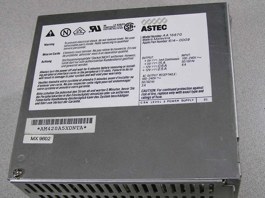
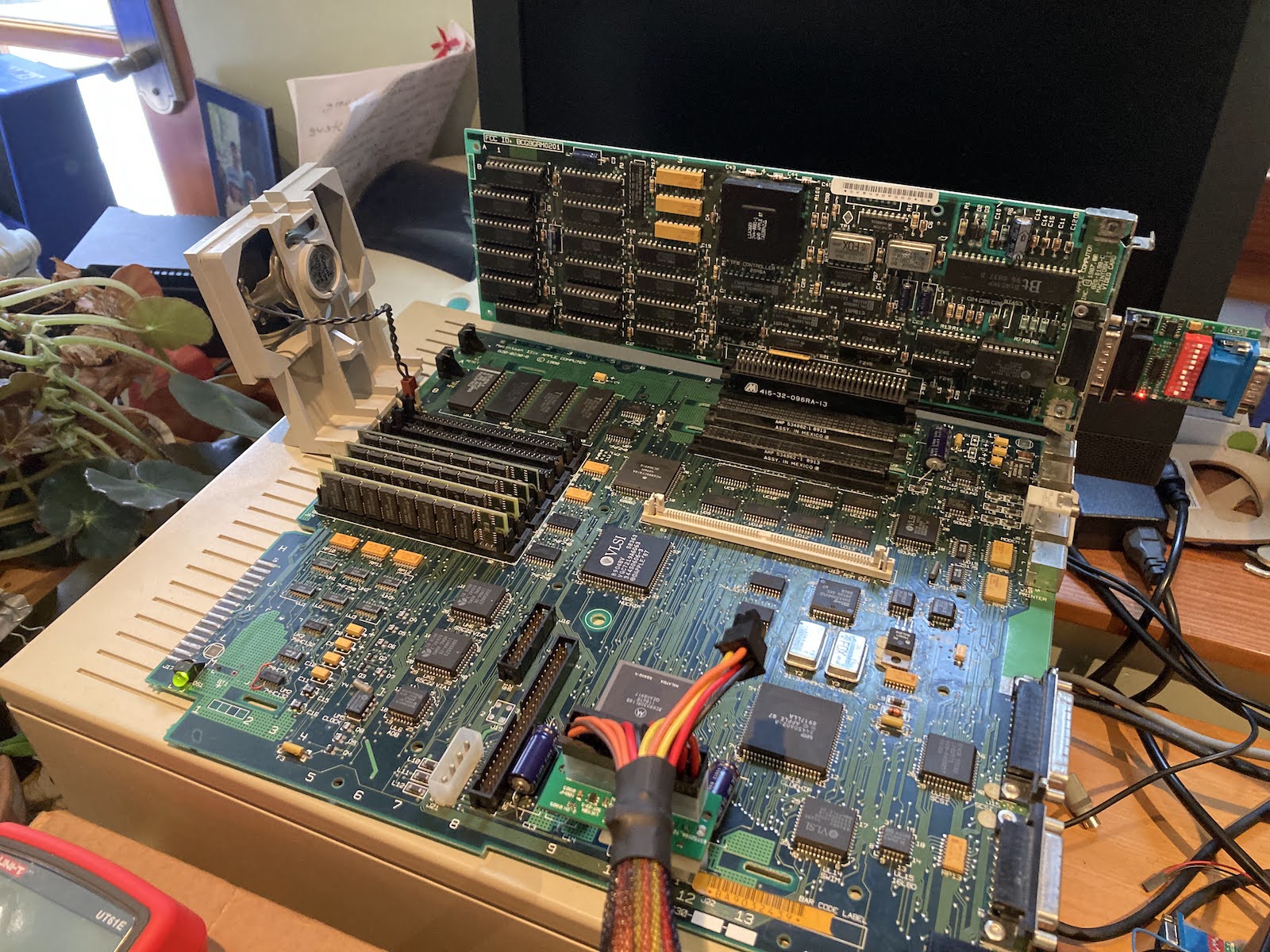
I’m trying to replace a Macintosh IIci/IIcx power supply, as shown in the photo above. With the help of a friend, I replaced it with this Logisys ATX PSU, and at first all seemed fine. But then I did some load tests in the Macintosh IIcx, adding more and more cards and peripherals while measuring the 5V and 12V supply regulation. The initial setup was a IIcx using the Logisys PSU, with 20MB RAM, no hard drives or floppy drives, no keyboard or mouse, no cards, and no ROM SIMM. I measured voltages at the empty hard drive power connector.
- initial readings: 4.932, 12.294
- +1 ethernet card, 1 ADB keyboard, 1 ADB trackball: 4.895, 12.302
- +1 Toby video card: 4.824, 12.327
- +1 Apple Hi-Resolution Display Card: 4.779, 12.340
- +2 BMOW Floppy Emus (internal and external): 4.763, 12.343
- +1 Zulu SCSI using term power: 4.742, 12.338
- +1 BMOW Wombat with attached USB hub, USB keyboard, USB mouse: 4.729, 12.343
- +1 12V fan rated 0.77W: 4.734, 12.325
Bolded values are out of spec. The additional load I was adding was all on the 5V supply, whose voltage kept sinking lower and lower while the mostly-unloaded 12V supply kept climbing higher. This is exactly what you’d expect from a PSU that uses group regulation, where all of the outputs are regulated using a single combined error feedback mechanism, instead of each output being independently regulated.
In the case of many common cheaper ATX PSUs, they are group regulated based on the combined error in the 5V and 12V outputs. In a severe cross-loading situation with lots of 5V load and minimal 12V load, the PSU is trying to split the difference by making 5V too low and 12V too high, which causes 5V to go out of spec. Adding a fan to create a small load on 12V helped a tiny bit. But extrapolating from that one fan, I’d need to add 41W of load on 12V to bring the 5V supply all the way up to where it should be.
The original stock PSU in the Macintosh IIcx and similar computers did not suffer this problem, and was presumably independently regulated. So what is the aspiring vintage computer PSU rebuilder to do here?
- Buy a much more expensive ATX PSU that is not group regulated, and that can supply enough amps on its 5V output (minimum 15A), and is small enough to fit the small physical dimensions inside the IIcx PSU enclosure. Finding options that tick all the boxes is difficult, and these may cost $100 or more. Most modern ATX PSUs can not supply enough current on their 5V output.
- Add a 12V dummy load using power resistors, something on the order of 10 to 40 Watts, to reduce the cross-loading between the 5V and 12V outputs. But what level of dummy load is correct? And what about the extra heat that will be generated?
- Design a custom PSU solution using a commercial 12V regulated supply plus a separate high-power buck converter for 5V, and another converter for -12V, and also something for 5V trickle and soft power like ATX’s PS_ON input.
- Something else clever that you may suggest.
10 Comments so far
Leave a reply. For customer support issues, please use the Customer Support link instead of writing comments.
You may want to try a server PSU…
Depending upon the design of the source supply, I’d suggest using a voltage reference, some resistors, a dual op amp, and a couple of power transistors, to make a circuit which would feed current from the twelve-volt rail to the five-volt rail if the former is at or above the upper limit, and feed current from the five volt rail to ground if it is at or above its upper limit. For the scenario where the 12 volt rail is under-loaded relative to the five volt rail, any current transferred from the former to the latter would reduce the amount of power the supply had to feed to the five-volt rail, which would in turn reduce the amount of power it would try to supply to the twelve-volt rail. The five-volt clamp would ensure that the twelve-volt clamp couldn’t try to pull the five-volt rail up too high.
PSUs following the old ATX1.x spec should be able to deliver 18 A and more at +5 V, and should regulate mainly (or only) the +5 V rail. Those PSUs usually lack the SATA power connector and the mainboard connector usually has only 20 pins, not 24 pins.
A different approach might be a ATX12VO supply (https://en.wikipedia.org/wiki/Power_supply_unit_(computer)#12_V-only_supplies), plus a tiny 78(L)05 or 7805-style switching module (e.g. Recom, Traco) to generate +5V standby from +12V standby, plus a small DC/DC converter to generate -12V from +12V, plus a beefy DC/DC converter to generate +5V from +12V. This way, all mains-related issues (lethal voltage, filtering, safety certificates) are contained in the ATX12VO PSU, and all voltages are properly regulated. Switching the ATX12VO PSU works like with a conventional ATX PSU: Pull down the PS_ON# signal.
Burning tens of Watts just to make the “wrong” PSU regulate properly is just wasteful.
I’m not sure if it can be trusted, but you can buy something that claims to be a five volt fifteen amp power supply on Amazon for $25. If you pair that up with a twelve volt supply then you might have what you need.
Sean, no, two single-voltage power supplies won’t do the trick. Unlike many other old Computers, and like all modern PCs, the Apple Macs don’t use a hard power switch (except perhaps on the back side). Instead, a small stand-by supply keeps a little part of the computer powered, just enough to be able to respond to the power button. That part switches the remaining part of the power supply on and off.
We had some more discussion about power supply design at the 68kMLA vintage Macintosh site. The consensus was an approach similar to Tux2000’s 12-volt-only suggestion, except starting with a 5-volt-only supply since most of the Mac’s demand is for 5V. Then we’d need to add a 12V boost regulator capable of a few amps, instead of needing a 5V buck regulator capable of ~20 amps. There’s a conceptual schematic / block diagram here: https://68kmla.org/bb/index.php?threads/designing-the-ideal-atx-power-supply-replacement-for-vintage-macs.45802/#post-508290
One disadvantage of starting with the +5 V supply is that all load peaks on the boosted +12 V hit the +5 V suppply about three times harder. This may also affect the +5 V regulation. (Why three times? Assume 12 V 1 A, that’s 12 W. 12 W at 5 V are 2.4 A. The boost converter has some losses, too. So assume an 80 % effective converter, 12 W output need 15 W input. 15 W at 5 V are 3 A.)
So if +12 V loads in and on the Mac cause load peaks (e.g. when switching DC or stepper motors), you will have some ripple on the +12 V line. The boost converter triples the load current (see above), and the harder load peaks on the +5 V will cause a lot more ripple on the logic supply.
Starting with a beefy +12 V supply, load peaks will still cause a some of ripple on the +12 V line, but as the supply is designed for larger loads, there will be less ripple from the same load peaks. Stepping the +12 V down to +5 V reduces load peaks from the +5 V line by about 50 %. (Just reverse the calculation: 5 V at 1 A are 5 W, 5 W at 12 V are 0.42 A, with an 80 % effective converter, 5 W output need 6.25 W input, that’s 0.52 A.)
And, all (or almost all) logic components are supplied from the +5 V rail, whereas the +12 V rail is usually used almost exclusively for driving mechanics (motors, coils) and amplifiers. None of those loads should be disturbed by a little bit of ripple.
The sketch from 68kmla.org more or less ignores the standby supply. It keeps the main +5 V PSU running all the time, and just limits the standby supply current by a polyfuse. Polyfuses are resistors, they have a negative effect on load regulation, and they suffer from overloads. (They are called polyfuses, not infinite fuses, for a reason.) But the main problem in that design is the main +5 V PSU running at minimal load. Switching PSUs aren’t very efficient in that situation, that’s why ATX supplies have a completely separate PSU in the same case for the standby supply, sharing only mains input and filtering.
The main fuse is nonsense. A 5 V switch-mode PSU capable of delivering 20 A to 30 A should be able to protect itself from overload and shorts. Also, it should be way faster at shutting down than a fuse. (Remember: Fuses that should protect semiconductors are usually protected by the semiconductors dying faster than the fuse can blow.)
The big switching MOSFET needs to withstand the full load current. It has a non-zero RDSon, so it will become at least warm, if not hot, depending on the MOSFET. Also, it must be switched very fast, because during the transition from on to off, the RDS will be significantly higher than RDSon, and the MOSFET will need to dissipate more heat. Switch too slow and the MOSFET will burn out. It is much more efficient to just turn off the switching supply at its contoller, like an ATX PSU does. Again, that needs a separate standby PSU.
The extra capacitors around the DC/DC converter should not be needed. A 5 V 20 A to 30 A PSU should be able to supply a 30 W to 40 W DC/DC converter without extra capacitors, and also that DC/DC converter should not need extra capacitors at its outputs.
The extra capacitors also limit the converters’ ability to switch off or limit current in case of an overload (the converters simply can not control them).
Overload behaviour – I’m very sure that the Apple PSU completely shuts down ALL non-standby outputs if it detects a short on ANY non-standby output. With this setup, shorting out +12 V or -12 V just disables one or both 12 V rails, but not the +5 V. Shorting the +5 V also disables the two 12 V rails and the standby supply.
My ATX12VO setup shares this problem: Shorting out the -12 V has no effect on +5 V and +12 V, shorting out the +5 V does not disable +12 V and -12 V. Shorting +12 V disables everything but the standby supply.
Off-topic: WordPress seems to crash on some of my comments, returning a 500 Internal Server Error. Shortening has helped, but a second comment crashed WordPress again, repeatedly.
Another way to build a PSU: Mains input through a filter with a common C14 connector input, preferably also containing a fuse and a switch. A small AC/DC module generating +5 V standby, directly connected to the mains filter output. A solid state relais switching at zero-crossing, capable of switching 200 W or more for mains input between 90 and 250 V, controlled by the Soft-Power-On signal from the Mac, either directly or using a transistor and one or two transistors. (The SSR input is just an LED and a current limiter.) An AC/DC module or open frame PSU for generating main +5 V, connected via the SSR to the filter output. An AC/DC module or open frame PSU for generating +12 V, also connected via the SSR to the filter output. A DC/DC converter module for generating -12 V from +12 V.
This setup shares the shorting problem. Shorting +12 V also disables -12 V, but all other rails are independent.
Unlike with an ATX PSU or a main PSU delivering power to the computer directly and via DC/DC converters, you need to distribute mains power in a safe, standards conforming way. Mains voltage may be between 100 V and 240 V (plus/minus tolerances), depending on where on the planet you are. The wires and connectors must be able to withstand the higher currents of 100 V mains, and the insulation must be sufficient for 240 V mains. Also, not all AC plugs and AC sockets in the world are polarized, so you can not be sure which wire has line voltage and which line is neutral, so both must be wired and insulated as if they carry line voltage.
And perhaps the easiest way of handling the situation: Use a major brand ATX PSU, instead of the cheapest chinesium you can find. Add an ATX-to-Mac adapter and you are done.
ATX PSUs are specified to deliver the main voltages (+3,3 V, +5 V, +12 V, and +5 V standby) with a tolerance of ±5 %. The aux voltages -5 V and -12 V may vary up to ±10 %. So if the Logisys PSU really drops down below +4.75 V, it is simply out of spec and should be returned to the vendor for repair or replacement.
It would be interesting to check the PWR_OK signal on pin 8 of the ATX connector. If the output voltages run out of spec, the signal should switch from +5 V to 0 V.