

Video Bringup: Part 2
Video works! Er, sort of. After fixing the HYSNC problem, I experimented with the palette chip, just to prove it was working. With a few bytes’ worth of changes, I was able to turn everything red.
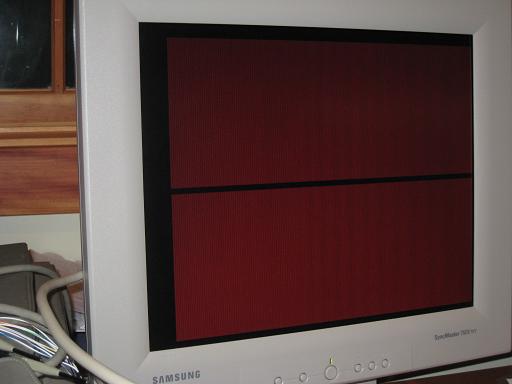
The monitor was still confused about the resolution, though, thinking it was 1152×864 when it was really 640×480. You can see in the photo above how the whole image appears twice on the screen. It should be a solid red screen.
After a little quality time with the oscilloscope, I discovered that my HSYNC fix hadn’t fixed anything at all, it had merely broken it in a different way. I reprogrammed the GAL that generates HSYNC, this time fixing the bug for real. Suddenly the monitor started showing pretty much what I expected: a screen full of garbage at 640×480. Success, of a sort.
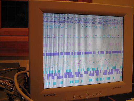
Now that things were behaving a little more sensibly, I started to worry about those light/dark vertical lines you can see in the image above. That’s not a result of the garbage data in video memory, as the lines extend straight through blocks of solid colors. It’s some kind of electrical noise creeping into the video output. It’s strange, because the lines are very “solid” and consistent, not blurry or wavy or intermittent like I would expect noise to be. I believe the 20MHz pixel clock is somehow leaking into the video output, because when I examined the VGA signal on the oscilloscope, the noise seemed to have have a 20MHz frequency. Maybe not though, because the lines aren’t just simple alternating light and dark bands, but are a repeating series of various lighter and darker vertical lines. So it seems I need some filter capacitors somewhere, or termination resistors, or a voodoo doll or something. Uh, yeah. This is basically why I’m a software guy and not an electrical engineer.
The analog VGA output is generated by a UM70C171 palette chip that I’ve mentioned several times before. I pulled it off an old video card that I dug out of the bottom of a box at Weird Stuff, a Silicon Valley warehouse of electronics junk. At the time I also bought a second old video card that had a chip made by Music Semiconductor, that I guessed was a UM70C171 clone, since its part number included the digits C171, it was the same size and shape, and the video card itself was similar. On a whim, I decided to try swapping in the Music chip, to see if it might be any more noise tolerant than the UM70C171. In retrospect, that was a little dangerous, since I really had no idea if the Music chip was some completely different IC that might fry BMOW when I swapped it in. But I threw caution to the wind, stuck in the mystery Music chip, and turned on the power. To my pleasure, not only did it work, but the noise seemed significantly reduced.
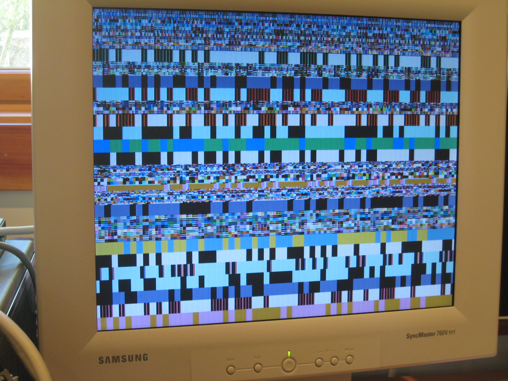
If you click the photo, you can view a larger version where the vertical noise bands are still visible. Areas that should be solid colors have thin vertical lines of varying brightness running through them. I really don’t know what causes this.
I decided to ignore the vertical lines for the moment, and set to work exercising the video modes. It’s funny, after having designed the video system, you’d think I’d know exactly what values to store where in memory to setup a particular mode or draw an image, but really I don’t. The video system schematics just prove that video is theoretically possible, but they don’t directly show you how to do it. It took me quite a while to figure out exactly where the video RAM and control registers mapped into memory, and what values to set in order make the right things happen. Honestly, I’ve only just begun to scratch the surface of it. I guess I need to write myself some documentation or a manual as I go.
Just poking bytes into memory using the monitor program, I was able to get things to happen, but I wasn’t always exactly sure what video mode I was in, or which options were currently enabled. So now I’ve reached the point where I can make things happen on the screen, but I’m not sure they’re quite what’s supposed to be happening. More time reviewing the schematics and GAL equations is needed to decipher it all. Why did I make this thing so darn complicated? I probably should have gone for a single video mode, at a fixed resolution and bit depth, and screw all this flexibility.
Nevertheless, I did get as far as clearing the screen, and turning on a single pixel in the center. I think this was in 128×480 @ 256 colors mode, but I’m not really sure. Help!
![]()
Next steps:
- Figure out what’s going on with those vertical lines, or learn to live with them.
- Reverse-engineer my own too-complicated design, so I can learn how to use it to create images.
- It seems as if the image is too dark by about 50%. What should be full white appears medium gray. I need to double-check the signal levels with the oscilloscope: they should be 0.7v for the analog VGA signals.
- Clearing the screen often causes the monitor to temporarily lose sync. Why? HSYNC and VSYNC should be unaffected by the contents of memory. Maybe some bus noise is causing false triggering of the sync signals?
- Depending on the method I use to clear the screen, it crashes BMOW. Hopefully that’s just a bug in my clear screen subroutine, and not another noise problem.
- Once all of the questions above are more or less resolved, I’ll add the character generator ROM so I can print some text.
11 Comments so far
Leave a reply. For customer support issues, please use the Customer Support link instead of writing comments.
I’d look that chip up and see how much current it can output.
Have you some buffers between the dac and monitor? Capable buffers? Avoiding possibly impractical solutions (sample & hold), I’d check out a video line displaying a solid color and have a look at these dips in voltage, maybe compare them with something.
As long as you’re addredding the chip right so it is always putting out a real value, not a transition, I don’t know.
This project has come a long long way!
Well I must say you are indeed moving in the right direction.
And half the battle is seeing something or other on your monitor.
The UM70C171 is meant to drive the VGA directly, and I’m using one of the output circuits suggested by the datasheet, mostly. I used 82 ohm termination resistors instead of 75, and I don’t have the quartet of filter capacitors between power, current source, and ground called for in the datasheet either. That’s probably half the problem. I tried jury-rigging a couple of the capacitors into the circuit, though, and it didn’t make much difference.
More progress, more problems:
– The crash while clearing the screen was caused by attempting to process an interrupt while the video RAM was the selected memory bank, which I hadn’t accounted for. Easily solved.
– The loss of video sync while clearing/writing the screen has proven very difficult to resolve. It seems that the row counter intermittently miscounts when the CPU accesses video RAM. Ugh.
– My choice of non-standard 512×480 as the highest resolution isn’t handled well by the built-in scaling hardware of my LCD monitor with 1280×1024 native resolution. When drawing one-pixel wide lines, some look wider than others. There’s probably not much I can do about that.
I’ve had a quick look at the datasheet for the UMC70C171 and it looks as if it will be very sensitive to noise on the IREF pin. The datasheet shows it decoupled to the VCC pin using a combination of capacitors. You could probably use a single modern 10uF ceramic capacitor instead. Keep the leads short. You could try glueing it under the chip and using short leads to connect it to the pins. An inch of wire here will likely make a lot of difference! The same goes for the VCC pin.
In addition, how you wire the UMC70C171 ground pin, the 75 Ohm resistors and the 0V to the monitor will be important too.
I’m looking forward to hearing how you get on. The noise problem should be soluble – don’t give up on it!
You might like to bear in mind that there is quite a lot of difference between and electrical engineer and an electronics engineer. People who mess about with tiny bits of silicon are firmly in the realms of electronics, whereas most electrical engineers are more interested in heavy bits of copper, power transformers, motor windings etc.
You might like to bear in mind that there is quite a lot of difference between and electrical engineer and an electronics engineer. People who mess about with tiny bits of silicon are firmly in the realms of electronics, whereas most electrical engineers are more interested in heavy bits of copper, power transformers, motor windings etc.
Well, there are no electronics engineering programs. You may be thinking of electronics engineering technology. That would deal more with semiconductor fabrication. Electrical engineering is not only concerned with power distribution. EE Encompasses RF, telecom, interface, consumer electronics…
At least in the USA. May be different elsewhere
I’ve not heard the term electronics engineer before. I did take some electrical engineering classes at MIT, but they were more theoretical. I think I did build an FM radio in a lab, though, and some other basic circuit projects. My degree was in computer science and engineering, which encompassed both software as well as digital logic and electronics labs. This was 15 years ago, so I’ve forgotten it all now anyway. 🙂
As for the UM70C171, Merlin is absolutely right that it needs decoupling capacitors, and I have none other than the one between power and ground that was already there. I tried jury-rigging some capacitors on the component side of the board using clip-on jumper wires, but it didn’t make much difference. Perhaps the wires were too long (about 12 inches). In truth it will be difficult to add capacitors with really short wires without relocating some other chips.
The output connection to the 75 Ohm termination resistors and the VGA connector is definitely poor. There are three long wires (for red, green, and blue) that snake the entire length of the board, almost 12 inches, crossing over hundreds of other lines that are undoubtedly introducing some noise.
I’ve stopped worrying about the noise for the moment. It’s distracting in large areas of solid color, but in a more complex image, it’s actually not too noticeable. I’ll come back and look at it again once everything else seems to be working.
My biggest problem right now is the loss of sync when accessing VRAM from the CPU. I’ve been looking at it for several days now, with no success. I’m using a GAL as a counter to count each row of the frame, and when the row count reaches 525, it asserts VSYNC. Unfortunately when the CPU takes control of VRAM and does a lot of reads/writes to it, it causes the GAL counter to miscount, making VSYNC jitter and causing the monitor to desync. Once the CPU access ends, it starts working fine again, and I can see the resulting image.
I’ve had similar problems before with GAL counters in the PC and the address register, and in both cases it was due to a noisy clock input. I’ve now tried several different ways of routing the clock input to the row counter GAL, but nothing seems to help. I may need to give up on using a GAL for this, and just use a standard counter, but that will eat up more of what little empty space is left on the board. It’s slow going, because each little experiment may involve adding and removing dozens of wires, only to find that it made no difference to the problem.
I notice that you have the odd pair of holes free next to most of the chips. Could you add extra decoupling there? An inch of wire will really make a difference here. Thicker wire also helps. Consider soldering capacitors directly between the wire-wrap pins and the copper ground plane of your PCB. Messy, but may be necessary for the faster chips. I have successfully wire-wrapped capacitor leads directly to pins before, then soldered the other end. Bad decoupling can cause all sorts of nasty problems! Don’t forget that the palette chip and faster GALs are almost certainly not designed with wire-wrap construction in mind, so you may have to be creative.
Another thing that can bite you is using logic gates in clocks. This can be done safely, but if you are not careful you can create very short “snicks” in the clock waveform that cause havoc. You will probably be able to see this if you have a fast ‘scope. Connect the leads as close to the chip as possible (including the ground) so you can “see what the chip sees”. Sometimes this can be quite alarming!
If you have a clock running down a long wire, you may have problems with reflections. Try to keep clocks short, but if desperate, try adding a small value capacitor (say 33pF) to the end of the line. Its a bit of a dodge, but if nothing else it may point out the problem. Sometimes just connecting the ‘scope is sufficient!
Running the video signals across the board is not ideal, as you realise. Could you replace this wire with some thin screened cable? That way, it would be relatively immune to the other digital signals. Even twisted pair cable would be an improvement.
It sounds as if the “electrical/electronics engineer” thing is a US/UK difference. Electronics engineers certainly exist over here – I know because I am one! I can make silicon do useful things, but am a bit out of my depth with heavy power, and my qualifications wouldn’t allow me to legally wire a house. That’s a different (but admittedly related) trade – a bit like plasterer and bricklayer.
I spent a few more minutes yesterday experimenting with decoupling capacitors to help eliminate the video noise. This time I bent the cap leads, and held them in place above the chip, with the leads touching the right pins. This way I could experiment with different capacitance values using short leads without actually wrapping or soldering anything.
I tried a variety of capacitance values between 0.01uF and 10uF. The value didn’t seem to make much difference. Putting a cap between the palette chip’s VCC and IREF current reference pins made very little difference, if any. Putting one between the palette’s VCC and GND pins did partially smooth out the noise, but it also made the remaining lose look more irregular, which is kind of annoying.
In retrospect, there may be multiple noise sources: one regular one at the palette chip, caused by the video clock, and a host of irregular ones on the VGA output lines as the cross the CPU logic lines, caused by CPU activity. The VCC to GND capacitor on the palette chip may have helped eliminate the first, making the second more noticeable?
The only saving grace here is that the noise problem is really not overly severe. It’s annoying, but unless you’re displaying large solid-colored regions, you hardly notice it.
Merlin, if its a trade thing such as carpenter/bricklayer, that would be electrician.
Steve, as for 12″ long video wires, you may have luck doing poor-man’s coax, sheathing the lines in alum foil or some sort of braid.
Then again, first thing that comes to mind is hookup wire rather than WW. Adding lots of caps shouldn’t be too hard of a problem on the underside of the board. Chances are that they will be hard to undo though if you need to.
Also, different monitors have different tolerances for different resolutions. I’ve never seen one that generates its own sync. That would be quite nice.
Good luck on the debug