

Adventures in Microcontroller Circuit Debugging
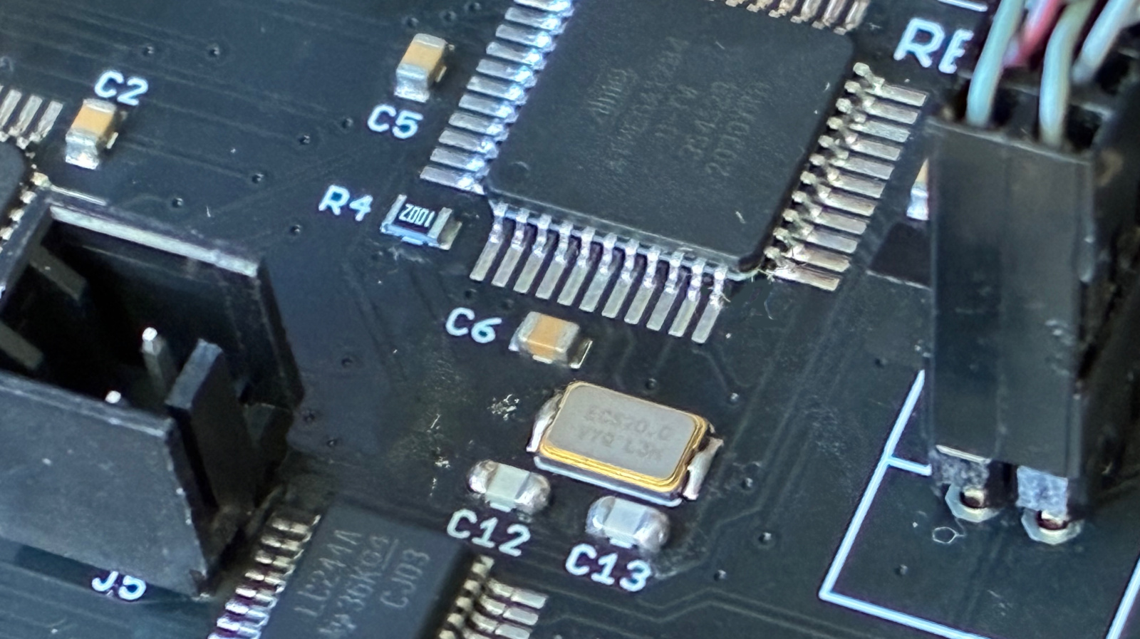
How do you go about troubleshooting a misbehaving microcontroller circuit? A few months ago I manufactured a new batch of Floppy Emu disk emulators. A number of them failed QA at the factory, with a set of symptoms that I’d never seen before in all my years of developing this device:
- Most of them simply wouldn’t boot up at all, despite verifying that power was good and the mcu was correctly programmed.
- Some exhibited “haunted” behavior, seemingly jumping to random sections of the mcu program code, outputting messages on the display that made no sense given the context.
- One of them appeared to work in slow motion, with LED blinking and display updates noticeably more sluggish than normal.
This was odd, to say the least. I have a lot of experience with the ATMEGA1284 microcontroller and the Floppy Emu circuitry that surrounds it, and I’ve become an expert at guessing what’s wrong based on the symptoms of misbehaving boards. These were all new and bizarre symptoms to me. Might they arise from different problems, or could they all point to one common underlying issue?
My intuition suggested some kind of systematic assembly problem. My contract manufacturer used a new subcontractor for this batch of Floppy Emu boards, so maybe a silent change to the process caused an unexpected issue? Parts substitution? Bad parts? Counterfeit chips? These QA failures sat in a pile on my desk for months, waiting for answers.
Probing, Poking, and Theorizing
Yesterday I finally decided to concentrate on the “won’t boot” devices, since that seemed like the most tractable problem. I put a few boards in a test harness, and connected power and a hardware debugger. The power supply voltages looked good. No obvious soldering problems were evident, but just to be sure I reflowed the solder on a few boards, without seeing any improvement.
On many of the boards, the hardware debugger could talk to the microcontroller and I was able to confirm the chip was correctly configured and programmed, but the program didn’t seem to actually run. At power-up the boards did… nothing. And with a smaller number of the boards, the debugger could not communicate with or even detect the chip. What could cause these symptoms? I brainstormed:
- Bad power. Seemingly ruled out by my measurements.
- Misprogrammed chips. I confirmed the configuration and reprogrammed several, without improvement.
- Bad chips.
- Chips stuck in reset.
- Clock problems.
- Problems with other circuit components (SD Card, CPLD, etc) causing electrical or program failures.
A batch of bad microcontroller chips seemed like the most likely explanation, so I desoldered the ATMEGA1284 from a board and replaced it with a new one from my stash. But after configuring and programming the chip, the board behaved the same as before, refusing to boot. That seemed to rule out problems with the chips themselves.
In the Floppy Emu program code, when the device first powers up, there’s some communication with the SD Card and the CPLD that happens before anything is drawn on the device display. I suspected that something might be going wrong during those steps, causing the program to freeze or crash and resulting in a blank display. To test this, I modified the program to blink the status LED twenty times as proof of life at the start of main() before doing anything else. Yes, with all the hardware tools at my disposal, I was back to caveman debugging with a blinking LED.
But there was still no joy, no LED blinking, no apparent program activity at all during power up. What the hell? Here I had a good microcontroller with good power, confirmed programmed correctly, in a circuit and board design that’s been in successful use for years. It wouldn’t even blink an LED. Since the blinking should have happened as the very first step of the program, its absence mostly seemed to rule out explanations related to failed interactions with other circuit components like the SD Card. So I focused in on the reset signal and the clock, the only two possibilities that I had left.
Clock Crystal Mysteries
Floppy Emu’s microcontroller uses an external 20 MHz crystal for speed and precision, but it also has an internal built-in 8 MHz oscillator. This particular board was still communicating OK with the hardware debugger, so for grins I tried changing the chip’s fuse configuration to select the internal 8 MHz oscillator as the clock source. Lo and behold, it worked! The device booted up and appeared to run normally, although obviously at only 40 percent of normal speed. I confirmed the same result with a few other boards – when I was able to get debugger communication and change the clock source to the internal oscillator, the board would boot. This wasn’t a fix, since the Floppy Emu won’t actually work correctly with an 8 MHz oscillator, but it was proof of major trouble with the external clock crystal.
If an external crystal isn’t working reliably, the microcontroller won’t have a reliable clock source. It will probably fail to run at all, or else act super glitchy. It will also cause problems with debugger communication. This all sounds a lot like my observed symptoms.
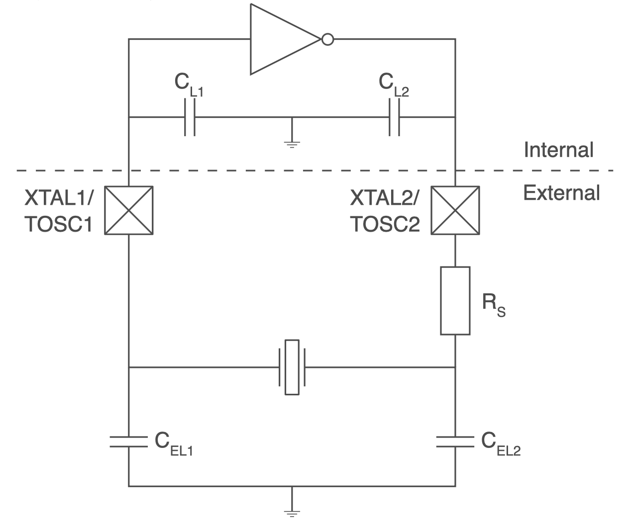
So let’s talk about this crystal oscillator circuit. Like almost all microcontrollers, the ATMEGA series has built in amplifier hardware to drive an external piezo crystal and force it to oscillate, using a circuit that I believe is called a Pierce Oscillator. I should know more about the theory of operation, but I’m mostly ignorant. What I know is that you connect the crystal’s two terminals to two ATMEGA pins using the shortest PCB traces that are practically possible, and add two external capacitors with values in the picofarad range, whose values are determined by a formula, and then everything works.
Investigating a bit further, I observed that all of the problem boards used a different crystal manufacturer than I have used previously. That’s fine, it shouldn’t have been an issue, but it seemed important given the circumstances. Previous editions of the board used this NDK crystal, but these troublesome boards substituted a similar ECS crystal. Both used the same physical footprint and advertised an 8pF load capacitance.
Speculations and Next Steps
As of today, that’s as far as I’ve gone with direct debugging, but I’m continuing to search for a smoking gun explanation. Maybe I got a batch of bad crystals? Possibly, and I can try reworking a board and replacing its crystal, but that explanation seems not very likely to me.
What about those two capacitors that form part of the oscillator circuit? Their values are important to the oscillator operation, and if the value is too far off from the optimal value, then the crystal won’t oscillate correctly or won’t oscillate at all. These tiny SMD capacitors bare no markings, so there’s no way for me to confirm visually that the capacitors are the correct ones. Maybe the subcontractor used the wrong value of capacitors on some boards? Speaking of which, what is the correct value?
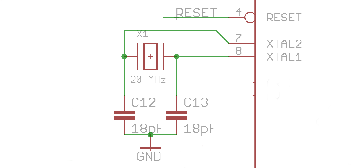
Here we enter into a bit of Pierce Oscillator analog voodoo that I don’t understand very well. The correct value of the two external capacitors is given by the formula Cext = 2 * (Cload – Cstray). Cload is the crystal’s load capacitance: 8pF in this case. Cstray is a measure of the stray capacitance of the microcontroller pins and PCB board traces. There’s no simple way to measure this directly, but for short traces on a two-layer PCB, I’ve seen estimates around 3pF to 5pF. Let’s call it 4pF. So Cext = 2 * (Cload – Cstray) = 2 * (8pF – 4pF) = 2 * (4pF) = 8pF. In theory then, I should have two external 8pF capacitors paired with the clock crystal. In reality, the capacitors are 18pF.
18pF external capacitors. I don’t remember how I originally specified this value; it’s lost in the mists of time during Floppy Emu’s initial development phase. But looking at it again now, it certainly seems “not ideal”. The oscillator circuit can be fairly forgiving and the ATMEGA driver amplifier can work over a broad range of capacitance values, which is probably why I never noticed an issue before. But 18pF is not mathematically correct. My guess is that the oscillator circuit has been operating close to the margins, and now there’s something different enough about this ECS crystal, its ESR or stray capacitance maybe, that pushes the circuit far enough out of its comfort zone that it stops working entirely.
So now what? How can I confirm this theory and fix the issue? One possibility is modifying the ATMEGA’s crystal driver behavior by changing a fuse setting. I normally use the low-power crystal oscillator mode, which applies a driving voltage in the millivolts range, but there’s also an option for full-swing crystal oscillator. In theory this setting should work better in cases like this where the external capacitors are outside the optimal range of values. To test this, I altered the fuses on one board to enable the full-swing oscillator behavior, and… it didn’t work. The board still wouldn’t boot up, and it also stopped communicating with the debugger, so it’s now effectively a brick.
That leaves me with the possibility of reworking the boards and swapping the external capacitors for 8pF replacements. Or maybe 10pF or 12pF if I want to stay closer to the original design value, since problems can also arise if the value is too low as well as if it’s too high. Unfortunately my workshop doesn’t stock any appropriate capacitors in that range. I’ve ordered a variety of values to use for testing, so the conclusion of this mystery will need to wait until then. Stay tuned…
Read 23 comments and join the conversation23 Comments so far
Leave a reply. For customer support issues, please use the Customer Support link instead of writing comments.
Yeah, I would agree with your conclusion about the 18pF capacitors being too high in this case. You probably just have been operating on the margins, and some crystals (and drive circuits) are more tolerant of that than others.
One “trick” for tuning this, and I wish I could remember whose appnote it’s from, is to on a decent sample of units, measure a clock out (from a different pin, pwm, etc) with a frequency counter. See if you can find a value that gets the average population to close on frequency. Since “incorrect” load capacitance pulls the frequency around, make use of that to measure the capacitance indirectly. It’s been shockingly linear in my experience. (More capacitance is generally slower).
Many frequency counters have decent clocks in them already, but I use a cheap GPSDO as a reference source since I’m usually using tighter tolerance crystals than this design. You probably can get away with anything with a clock accuracy of 10ppm for measurement.
Good idea for clock tuning, thanks! As a test, I transplanted one of the previous model of crystal into the bricked board, and it immediately started working. If there was any doubt, this confirms that we’re dealing with a clock oscillator problem. But we still don’t know yet whether it’s due to a bad batch of clock crystals, or due to a mismatch between the new model of crystal and the external capacitor values. The capacitor value explanation seems much more likely, but it’ll be a few days until I can test it and verify.
If you really wanted to test the capacitor theory sooner, you could try soldering two 18pF caps like /\ on the pads.
It does seem worth noting that Microchip also suggests using the Full-Swing Oscillator at 20MHz. At least in Tables 9-3 (pg 41) and 9-5 (pg 42) of DS40002070B.
As for their suggested load capacitor ranges given, I’d interpret that as a suggestion to use a crystal with a higher intended load capacitance, not to run a low capacitance one above nominal. My understanding is that a higher target crystal load capacitance makes the system more stable to variations in capacitance (but costs power).
All that said, using either crystal with the right caps *should* be fine, even if the datasheet might imply otherwise. Besides, if you include the parasitics in the recommended values, then the total C1/C2 is right on the money anyway.
I’d never noticed that the low power crystal oscillator appears to be tuned for speeds 16 MHz and lower, according to that table. In Microchip Studio when configuring the oscillator, that configuration is shown as 8.0MHz- with no upper end of the range given. That’s good to know if I ever reuse this chip for a new design, but I’m not going to switch to the full-swing configuration now for fear of unintended consequences with a new setup.
How strange that Microchip recommends a range of 12pF to 22pF for the external capacitors, apparently without regard to the characteristics of the board or the specific crystal chosen. Maybe this is where I originally came up with the 18pF value, rather than by applying any formula.
Are you saying that you interpret those suggestions of capacitance value as applying to the selection of the crystal itself, choosing a crystal with a specific load capacitance, rather than to the selection of the two external capacitors? I thought the title of the table seemed pretty clear that it was about the capacitors.
Searching the web for info specific to ATMEGA crystal circuits, rather than generic abstract discussions of Pierce oscillators, I see a lot of people recommending values around 18pF to 22pF. That’s similar to what I already have now, and very different from what I calculated by the formula. Perhaps I’m not applying the formula correctly or have misunderstood something.
The XTAL1 pin is an input. Disconnect the quartz and the cap at that pin, and inject 20 MHz at roughly logic level from a function generator or an integrated quartz oscillator (typically comes in a four pin tin can). That gives you a stable clock and should allow unbricking.
Also, the ATmega1284 allows parallel programming, sometimes also called high voltage programming. It is enabled by tieing the RESET line to +12V. You may need to disconnect your watchdog / reset circuit from that pin to prevent damages. But in general, if you “just” messed up the clock settings, an external oscillator is sufficient.
Sorry, I wrote my last comment when I really should have gone to bed instead and so wasn’t as clear in hindsight.
“That’s good to know if I ever reuse this chip for a new design, but I’m not going to switch to the full-swing configuration now for fear of unintended consequences with a new setup.”
Agreed here. Between that things have worked with it (up until now) and the note in AVR studio you followed, leaving this alone is a low risk, and not your problem anyway.
AVR042/AN2519 (AVR Hardware Design) recommends even higher load capacitor values. But also says “Recommendations given in this chapter are guiding values only. Always check the data sheet, and calculate values accordingly [using the formula you are using].”
This makes me wonder if crystal desired load capacitances have gone down over the years, and much of this is just based on what parts were available when the chips were designed. I did a quick check, and for 20MHz PTH crystals, 18pF load capacitance is far and away the most common I saw, which would want a nice high capacitor value. Couple that with the classic error I see folks (and not just hobbyists) make of using caps of the same value as the specified load capacitance, and that all could be consistent with both of our observations.
“I thought the title of the table seemed pretty clear that it was about the capacitors.”
Yeah, this is where I made I mess of my statement. I think they were thinking of a (family of) crystal(s) with a specific load capacitance, and said “use this capacitance” without ever specifying the other half of the constraint (the crystal itself).
“Perhaps I’m not applying the formula correctly or have misunderstood something.”
I would trust the formula/physics and the measurements (both “it doesn’t work” and frequency measurements) over anything that gives values without also telling you what crystals to use. Both documents assume you have access to the same crystals they do.
Thanks again. Yes I think you’re probably spot on about this being a historical quirk. When the datasheet was written a decade or two ago, I suspect the most common package for crystals was the famous HC-49/US can. Given that assumption, the datasheet table’s higher range of external capacitor values makes some sense.
I replaced the 18pF capacitors on one of the non-working boards with 10pF capacitors, but it still doesn’t boot or respond to the debugger. That surprised me – I thought that was the answer! It was a rush rework job and I made a bit of a mess of it, including accidentally desoldering and reinstalling the crystal, so I’ll try again later with another board. But it appears that the capacitor value may not have been the issue after all. Either 10pF is a bad value, or it’s the crystal itself that’s at fault, or I’ve failed somewhere in my troubleshooting reasoning. Hmm.
Drat, I was really hoping for the easy fix. Good luck.
More documenting for my sanity… I installed 10pF capacitors on a second board, more carefully this time. This board originally had slightly different symptoms from the other one: it wouldn’t boot, but unlike the first board, it did respond to the debugger. After installing the new capacitors, it booted but behaved oddly. It sometimes complained the detected CPLD version 34 did not match the expected version 34 (huh?), or while traversing the SD card directory suddenly the screen would go blank.
I changed the clock source to the internal 8 MHz oscillator, and it began to work normally (but slowly).
I then changed the clock source back to the 20 MHz external crystal, but enabled the internal div-by-8 clock divider, so the effective clock speed was 2.5 MHz. I hoped this would reveal whether the problem was the higher speed supplied by the external crystal, or the crystal itself and its support capacitors. At 2.5 MHz with the external crystal everything seemed to work OK (but super slowly).
Finally I went back to the standard 20 MHz external crystal config, but with the full swing oscillator setting instead of low-power oscillator. This worked well.
Now it’s getting late and I’m not thinking entirely clearly, but I’m not sure what conclusions to draw from all this. This seems to point to the source of the problem being somewhere else: the AVR microcontroller (which I thought I’d ruled out by swapping one earlier) or maybe multiple simultaneous problems.
Another day, more data. I replaced the crystal on the first board: the one that wasn’t booting or responding to the debugger even after replacing the 18pF capacitors with 10pF. I installed the exact model of crystal used in older Floppy Emus. And it worked! I tested everything fairly thoroughly and it seems solid.
It’s still not 100 percent clear to me, but I now suspect the primary problem is with the crystal itself rather than the 18pF capacitors. Yes 18pF is not the right value, but I think it’s not actually a problem, or at least not the main problem. Maybe a difference in ESR value between the two models of crystal means one works OK in low power oscillator mode, but the other is iffy. Or for other reasons yet to be determined, this newer model of crystal just doesn’t play nice with the Floppy Emu circuitry.
I’m going to order more crystals of the old model, do some more crystal swapping, and see what happens.
If PB1 is safe to drive as an output clock, try enabling the CKOUT fuse per section 9.10 and probe it, on any boards that communicate to the programmer. Scope should be good enough for erratic behavior and checking nominal frequency. Using CKOUT means that you aren’t disturbing the circuit itself.
YMMV depending on the scope you have.
Also, this is supremely weird, it’s not just you. I’m definitely at a loss for good ideas at this point.
I don’t know if this is a helpful comment but reading the article and then quickly the comments here you considered the possibility of a faulty MCU but even with direct evidence pointing to the crystals as the problem discounted the idea they might be faulty. That seems like an odd choice to me. Crystals are in some ways quite delicate being physically tuned electro mechanical machines they can get damaged by all sorts of electronic and mechanical means. I’d bet you $20 the new crystals you ordered solve everything and if you test the faulty ones you find some very odd signal.
You’re right, it could be bad or damaged crystals. I didn’t give the idea too much thought, only because I’ve never encountered a bad/damaged crystal in any of the more than 10,000 boards I’ve made previously, and it would surprise me to suddenly have dozens of crystal failures. But maybe something went badly with the most recent batch. They were assembled by a different contractor, and they also used a different manufacturer of crystals, although with virtually the same specs as the crystals used previously.
Did the new contractor ultrasonic clean assembled boards?
Good thought about ultrasonic cleaning. I don’t know if it was used.
I’ve now gone through seven more problem boards. Five of these were fixed by swapping the crystal for the old style of crystal. Of these five, three could also be fixed before the crystal swap by changing the oscillator setting from low power to full swing, but two did not improve under the full-swing setting.
Two more boards are still not working even after a crystal swap, and also don’t work with the internal RC oscillator either. Their problem seems to be something unrelated to the clock. Their symptoms are different as well. One launches directly into the bootloader every time, as if the PREV and SELECT buttons were both pressed. The screen display is also frequently garbled. The other refuses to enter the bootloader when RESET is pressed, but will enter the bootloader from first power-up. It also freezes whenenver I attempt to program the CPLD.
I’ve enjoyed this and I feel your pain. I remember playing with old surplus WWII crystals (these were big;about this size of your thumb) as a Ham. We used to move frequency up by applying water and ajax cleanser to raise it, and applying pencil lead to lower it. The load capacitance affects frequency. Too far off and the crystal can stall or start behaving erratically. I mention this because it is important to remember that crystals are mechanical devices that do their magic by vibrating. They can be damaged by too much current, or being subjected to too much heat externally. I wonder if these were properly rated for the type of soldering used? Did they suffer an extreme temperature after manufacture? Damage in transit? I’d want to ask the contractor why the crystal was changed. Was it availability? Or cost (i.e. were they cheaper).
Chris
Chris
The clock crystals were changed in the most recent manufacturing batch because the regular crystal was temporarily out of stock. But I approved the change and believed they were equivalent, having the same speed rating and package size and load capacitance, with only a small difference in ESR.
But I think I’ve found the smoking gun that points to crystal damage during assembly. On many of the boards with crystal / clock problems, there is a fuzzy gray dot in the center of the crystal package. This is not supposed to be there, and doesn’t look like an intentional mark with a pen. I’ve seen something similar before in damaged ICs, and I’m fairly sure this is a sign of a component that was so hot that it burned the packaging, which virtually always means the component was damaged or destroyed.
I wouldn’t call the mystery 100 percent solved however, because some of the boards with clock problems don’t show this dot, and other boards that do show a dot are still working OK.
Can always try hotairing one of the new crystals to see when you get that burned dot.
That does align with my suspicions. As to the presence or absence of the gray blotch, the absence doesn’t necessarily disprove the theory. Crystals are electro-mechanical devices. There can be variations in production that may make some more susceptible to heat damage, or less. It could be that some withstood the abuse better than others and some were more fragile. A subtle difference would not necessarily show up in manufacture and the device might still make specification in testing. Just spitballing here. Possible scenarios besides not rated for the soldering temperature could include damage after manufacture, although I would think it would take a great deal of external heat to do this. Exposure to a strong A/C magnetic field? If possible I’d try to contact the manufacturer (China? Good luck!) or their US rep.
Good Luck
Chris
One out of left field. Examine a couple of the working boards the way the crystal is soldered. The closeup of the crystal seems to show there is a difference in the solder to the crystal and the surrounding components. Could it be that when there were shortages of the original crystal, the boards were assembled without the crystal and when they became available were added later. That might explain the fuzzy dot, they used a glue to manually hold the crystal. on one of the boards that doesn’t work, carefully remove the crystal and look at the connections, though by removing the crystal you are disturbing the tracks/solder anyway.
I had a similar problem with a DSP that used the third overtone of a 27MHZ crystal. It had to boot at a 24 hr colad soak at -40F for Northern border. Similar attempts to fix as yours all failed. The answer was a 1Meg resistor across the crystal terminals to bias the input and output of the crystal drive pins. This does not take much. Maybe even a 10Meg would do and still allow the low power drive settings to work (IE no code change). Test over temp. Freeze spray to hot air gun or use environmental chamber. Break it on the bench (and fix it before you ship) not at alpha, beta, or customer sites. Most production designs must work with a list of second sources so it is not the crystal.
I publish the Ajun industry-diagram site. The later comments materially change the early capacitor hypothesis, so a troubleshooting diagram should be a timeline rather than a single final-looking tree. I’d attach the board identifier, clock configuration and observed result to each test, with suspected cause kept separate from replacement outcome. That would show why the internal-oscillator experiment narrowed the problem while avoiding a claim that the first plausible capacitance calculation solved every failure.